100%
EG–465
ENGINE – 2JZ–GE ENGINE TROUBLESHOOTING
ECM Power Source Circuit
CIRCUIT DESCRIPTION
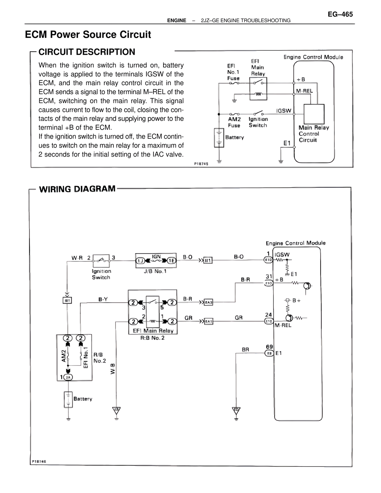
When the ignition switch is turned on, battery voltage is applied to the terminals IGSW of the ECM, and the main relay control circuit in the ECM sends a signal to the terminal M–REL of the ECM, switching on the main relay. This signal causes current to flow to the coil, closing the contacts of the main relay and supplying power to the terminal +B of the ECM.
If the ignition switch is turned off, the ECM continues to switch on the main relay for a maximum of 2 seconds for the initial setting of the IAC valve.
Engine Control Module
EFI
No.1
Fuse
EFI
Main
Relay
+B
M-REL
AM2
Fuse
Ignition
Switch
IGSW
Main Relay
Control
Circuit
Battery
E1
P18745
WIRING DIAGRAM
Engine Control Module
W-R 2 3
Ignition
Switch
IGN
1J 1E
J/B No.1
B-O
>>I11
B-O
1
IGSW
E10
E1
B-R
31
+B
E10
B-Y
2 2
3 5
B-R
>>EA3
B+
2 2
1
GR
>>EA1
GR
24
M-REL
E10
EFI Main Relay
R:B No.2
AM2 EFI No.1
R/B
No.2
W B
BR
69
E1
E9
1 2A
Battery
P18746