100%
EG–598
ENGINE – 2JZ–GTE ENGINE TROUBLESHOOTING
TE1 TE2 Terminal Circuit
CIRCUIT DESCRIPTION
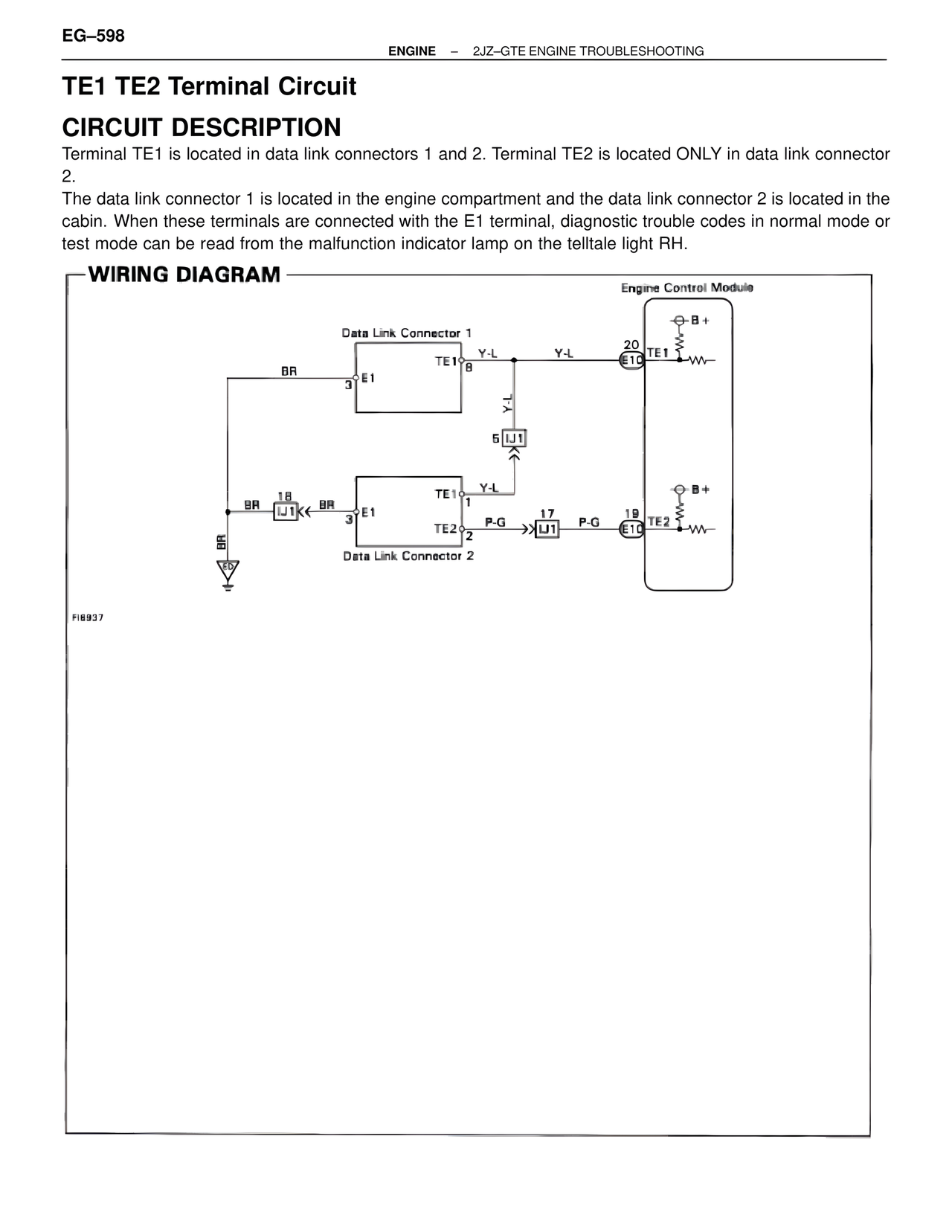
Terminal TE1 is located in data link connectors 1 and 2. Terminal TE2 is located ONLY in data link connector 2.
The data link connector 1 is located in the engine compartment and the data link connector 2 is located in the cabin. When these terminals are connected with the E1 terminal, diagnostic trouble codes in normal mode or test mode can be read from the malfunction indicator lamp on the telltale light RH.
WIRING DIAGRAM
Engine Control Module
B+
Data Link Connector 1
TE1 8
Y-L Y-L 20 E10 TE1
BR
3 E1
Y-L
5 IJ1
BR 18
IJ1 BR
3 E1
TE1 1
Y-L
B+
TE2 2
P-G 17 P-G 19 E10 TE2
IJ1
BR
Data Link Connector 2
FI6937