Page text (OCR transcript)
EG–542

ENGINE – 2JZ–GTE ENGINE TROUBLESHOOTING

WIRING DIAGRAM

B-R

Engine Control Module

GR
GR
24
B+
E10
M-REL

8
EA1

2
2

R/B No. 2
5

Main Relay

B-R
5
EA2
B-R

W
48
OX1
E9

2
3
Main Heated
Oxygen Sensor
E1

B-R

EF1 Main Relay

3

20 J1

B-R

71
HT1
E9
1
4
B-L
EO1

2
2

R-L
9
R-L
14
C1
J2

W

R-L
47
OX2
E9

Data Link
Connector 2
ENG 7
LG

R/B No. 2
4
C1

B-R
2
3

EFI No.1

E1

Sub Heated
Oxygen
Sensor

13 J1

12A

BR-W
5
72
HT2
E9
5 V

1
4
BR-W
C1
BR-W
J2

BR-W

8

W-B

4
15
LG
L3
OX1 OX2
29
VF1
E9
EO1

BR
8
BR
18
BR
C1
J1
VF1 13

Battery

BR

E1

Data Link
Connector 1

FI6918

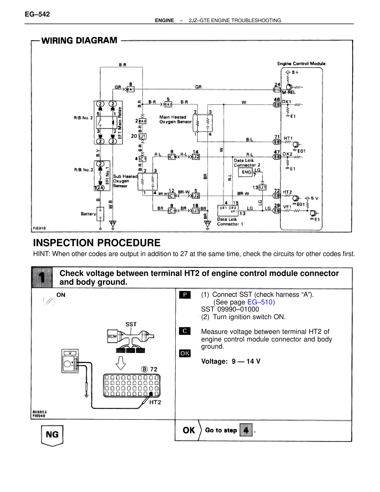
INSPECTION PROCEDURE

HINT: When other codes are output in addition to 27 at the same time, check the circuits for other codes first.

1
Check voltage between terminal HT2 of engine control module connector
and body ground.

ON

P
(1) Connect SST (check harness "A").
(See page EG–510)
SST 09990–01000
(2) Turn ignition switch ON.

SST

ECM

C
Measure voltage between terminal HT2 of
engine control module connector and body
ground.

OK

Voltage: 9 — 14 V

B 72

HT2

BE6853
FI6948

NG
OK
Go to step 4.