100%
Page text (OCR transcript)
EG–544

ENGINE – 2JZ–GTE ENGINE TROUBLESHOOTING

DTC 31 Mass Air Flow Meter Circuit

CIRCUIT DESCRIPTION

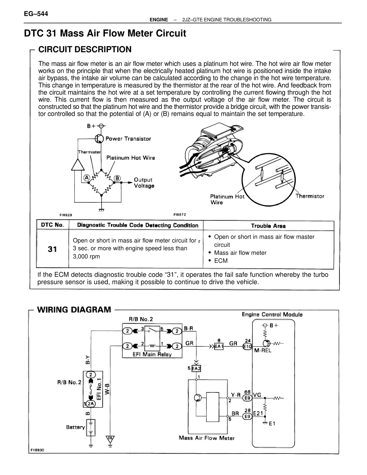
The mass air flow meter is an air flow meter which uses a platinum hot wire. The hot wire air flow meter works on the principle that when the electrically heated platinum hot wire is positioned inside the intake air bypass, the intake air volume can be calculated according to the change in the hot wire temperature. This change in temperature is measured by the thermistor at the rear of the hot wire. And feedback from the circuit maintains the hot wire at a set temperature by controlling the current flowing through the hot wire. This current flow is then measured as the output voltage of the air flow meter. The circuit is constructed so that the platinum hot wire and the thermistor provide a bridge circuit, with the power transistor controlled so that the potential of (A) or (B) remains equal to maintain the set temperature.

B+
Power Transistor
Thermistor
Platinum Hot Wire
A
B
Output Voltage

FI6929
FI6972

Platinum Hot Wire
Thermistor

DTC No. | Diagnostic Trouble Code Detecting Condition | Trouble Area

31 | Open or short in mass air flow meter circuit for 3 sec. or more with engine speed less than 3,000 rpm | • Open or short in mass air flow master circuit
• Mass air flow meter
• ECM

If the ECM detects diagnostic trouble code "31", it operates the fail safe function whereby the turbo pressure sensor is used, making it possible to continue to drive the vehicle.

WIRING DIAGRAM

R/B No.2
Engine Control Module
2  3  5  2  B-R
B+
2  2  1  2  GR
8  GR  24
EA1  E10  M-REL
EFI Main Relay
5 EA2
B-Y
R/B No.2
W-B
EFI No.1
2A
B
Battery

Y-R  66  VG
2  E9
BR  28
5  E9  E21
E1

Mass Air Flow Meter

FI6830