100%
EG–550
ENGINE – 2JZ–GTE ENGINE TROUBLESHOOTING
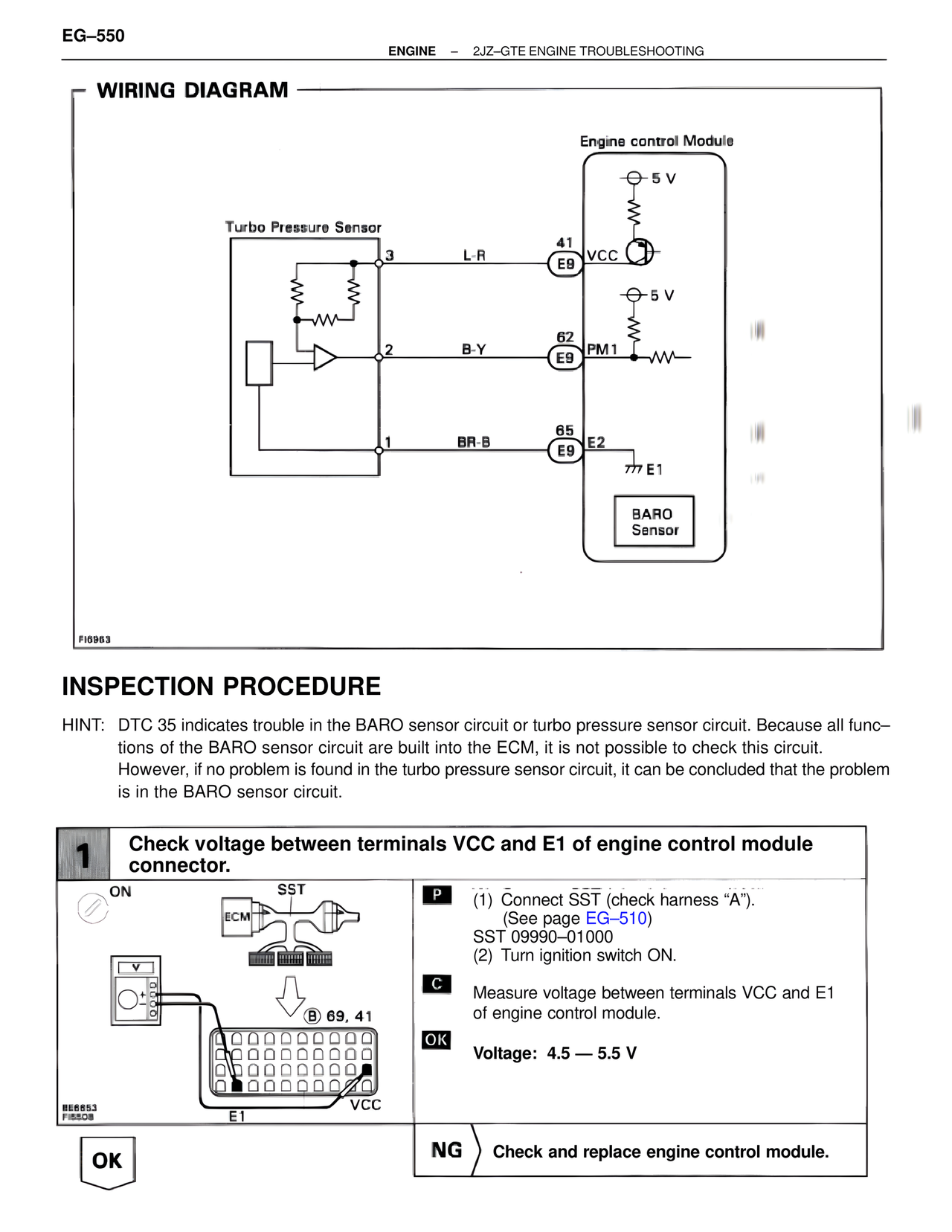
WIRING DIAGRAM
Engine Control Module
5 V
Turbo Pressure Sensor
3 L-R 41
E9 VCC
5 V
2 B-Y 62
E9 PM1
1 BR-B 65
E9 E2
777 E1
BARO
Sensor
FI6963
INSPECTION PROCEDURE
HINT: DTC 35 indicates trouble in the BARO sensor circuit or turbo pressure sensor circuit. Because all func–
tions of the BARO sensor circuit are built into the ECM, it is not possible to check this circuit.
However, if no problem is found in the turbo pressure sensor circuit, it can be concluded that the problem
is in the BARO sensor circuit.
1 Check voltage between terminals VCC and E1 of engine control module
connector.
ON SST
ECM
P (1) Connect SST (check harness "A").
(See page EG–510)
SST 09990–01000
(2) Turn ignition switch ON.
B 69, 41
C Measure voltage between terminals VCC and E1
of engine control module.
OK Voltage: 4.5 — 5.5 V
BE6853
FI6508
E1 VCC
OK NG Check and replace engine control module.