100%
EG–554
ENGINE – 2JZ–GTE ENGINE TROUBLESHOOTING
INSPECTION PROCEDURE
HINT:
• If diagnostic trouble code 41 is displayed, check throttle position sensor circuit. If diagnostic trouble code 47 is displayed, check sub–throttle position sensor circuit.
• If diagnostic trouble code "22" (engine coolant temperature sensor circuit), "24" (intake air temperature sensor circuit) and "41" (throttle position sensor circuit) are output simultaneously. E2 (sensor ground) may be open.
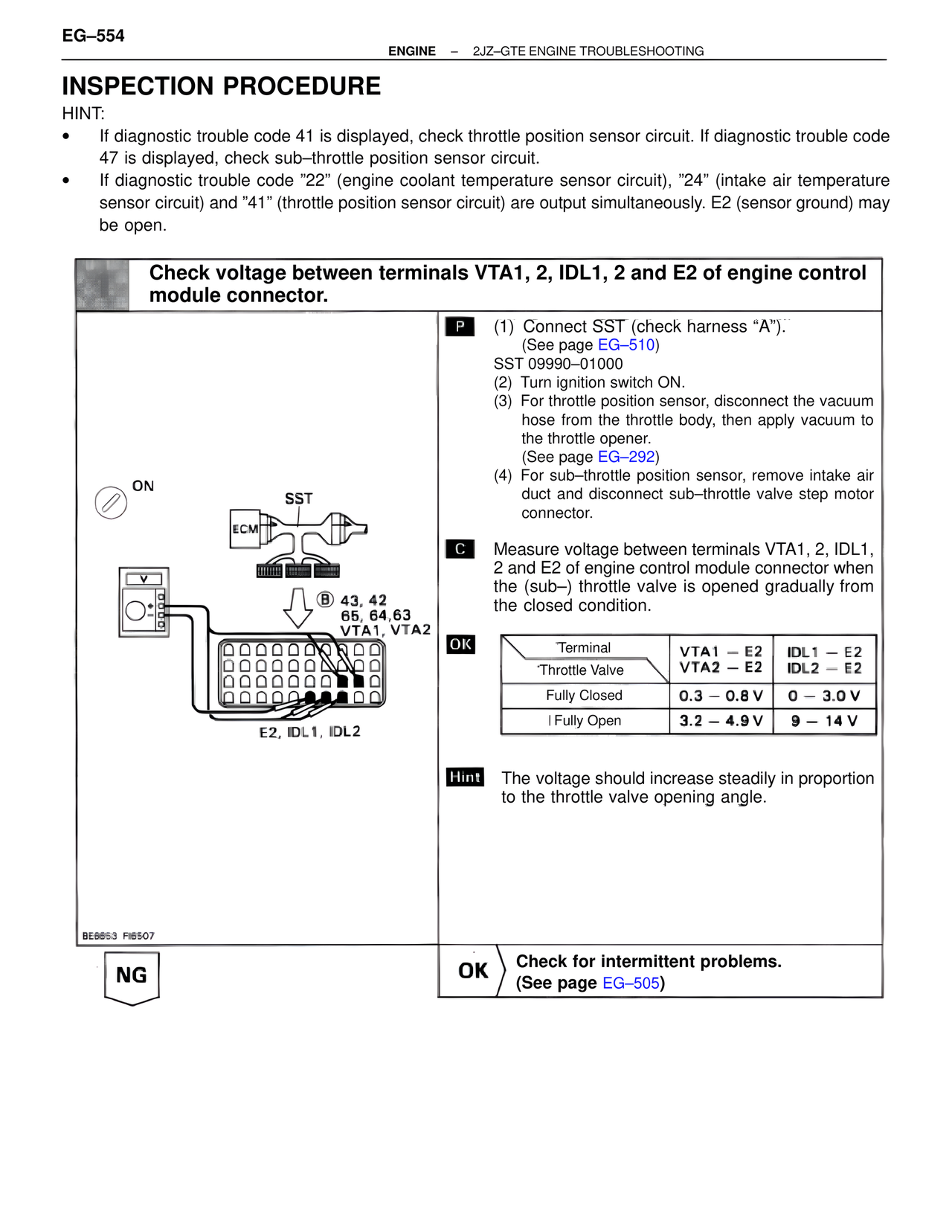
Check voltage between terminals VTA1, 2, IDL1, 2 and E2 of engine control module connector.
ON
SST
ECM
B 43, 42
65, 64,63
VTA1, VTA2
E2, IDL1, IDL2
BE6653 FI6507
P (1) Connect SST (check harness "A").
(See page EG–510)
SST 09990–01000
(2) Turn ignition switch ON.
(3) For throttle position sensor, disconnect the vacuum hose from the throttle body, then apply vacuum to the throttle opener.
(See page EG–292)
(4) For sub–throttle position sensor, remove intake air duct and disconnect sub–throttle valve step motor connector.
C Measure voltage between terminals VTA1, 2, IDL1, 2 and E2 of engine control module connector when the (sub–) throttle valve is opened gradually from the closed condition.
OK
Terminal VTA1 – E2 IDL1 – E2
Throttle Valve VTA2 – E2 IDL2 – E2
Fully Closed 0.3 – 0.8 V 0 – 3.0 V
Fully Open 3.2 – 4.9 V 9 – 14 V
Hint The voltage should increase steadily in proportion to the throttle valve opening angle.
NG
OK Check for intermittent problems.
(See page EG–505)