Page text (OCR transcript)
EG–559
ENGINE – 2JZ–GTE ENGINE TROUBLESHOOTING

DTC 43 Starter Signal Circuit

CIRCUIT DESCRIPTION

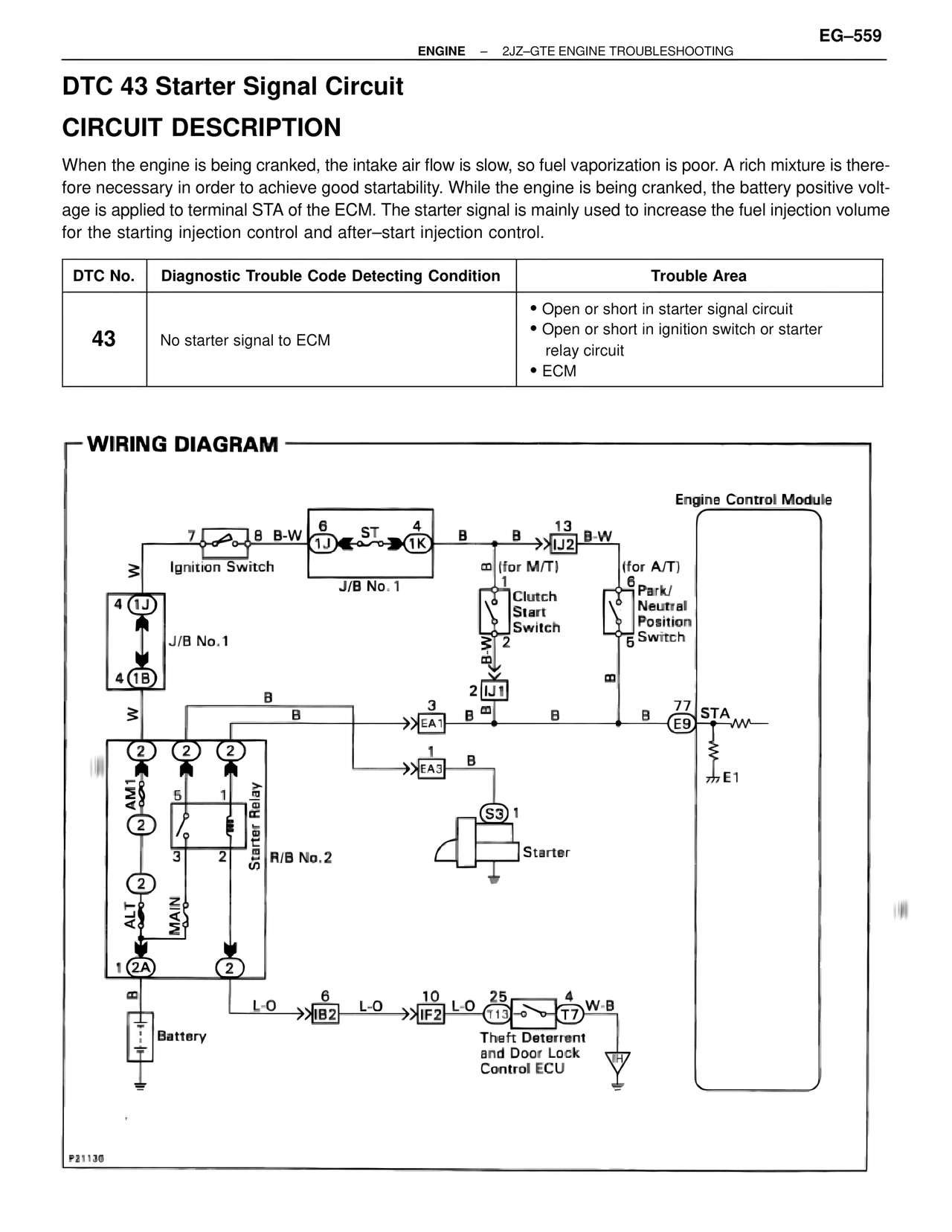
When the engine is being cranked, the intake air flow is slow, so fuel vaporization is poor. A rich mixture is therefore necessary in order to achieve good startability. While the engine is being cranked, the battery positive voltage is applied to terminal STA of the ECM. The starter signal is mainly used to increase the fuel injection volume for the starting injection control and after–start injection control.

DTC No. | Diagnostic Trouble Code Detecting Condition | Trouble Area
43 | No starter signal to ECM | • Open or short in starter signal circuit
• Open or short in ignition switch or starter relay circuit
• ECM

WIRING DIAGRAM

Engine Control Module

7 8 B-W 6 ST 4
1J 1K
Ignition Switch
J/B No. 1

4 (1J)
J/B No.1
4 (1B)

B B 13 B-W
>>IJ2
B (for M/T)
1
Clutch
Start
Switch
B-W
2

(for A/T)
6
Park/
Neutral
Position
5 Switch

B

2 IJ1
B B

W B

2 2 2
AM1
2
5 1
Starter Relay
3 2
R/B No. 2

3
>>EA1 B B B 77
E9 STA
1
>>EA3 B

(S3) 1
Starter

77 E1

ALT
MAIN

1 (2A)
2

B
L-O 6 L-O 10 L-O 25 4 W-B
>>IB2 >>IF2 T13 T7

Battery

Theft Deterrent
and Door Lock
Control ECU

P21136