Page text (OCR transcript)
EG–562
ENGINE – 2JZ–GTE ENGINE TROUBLESHOOTING

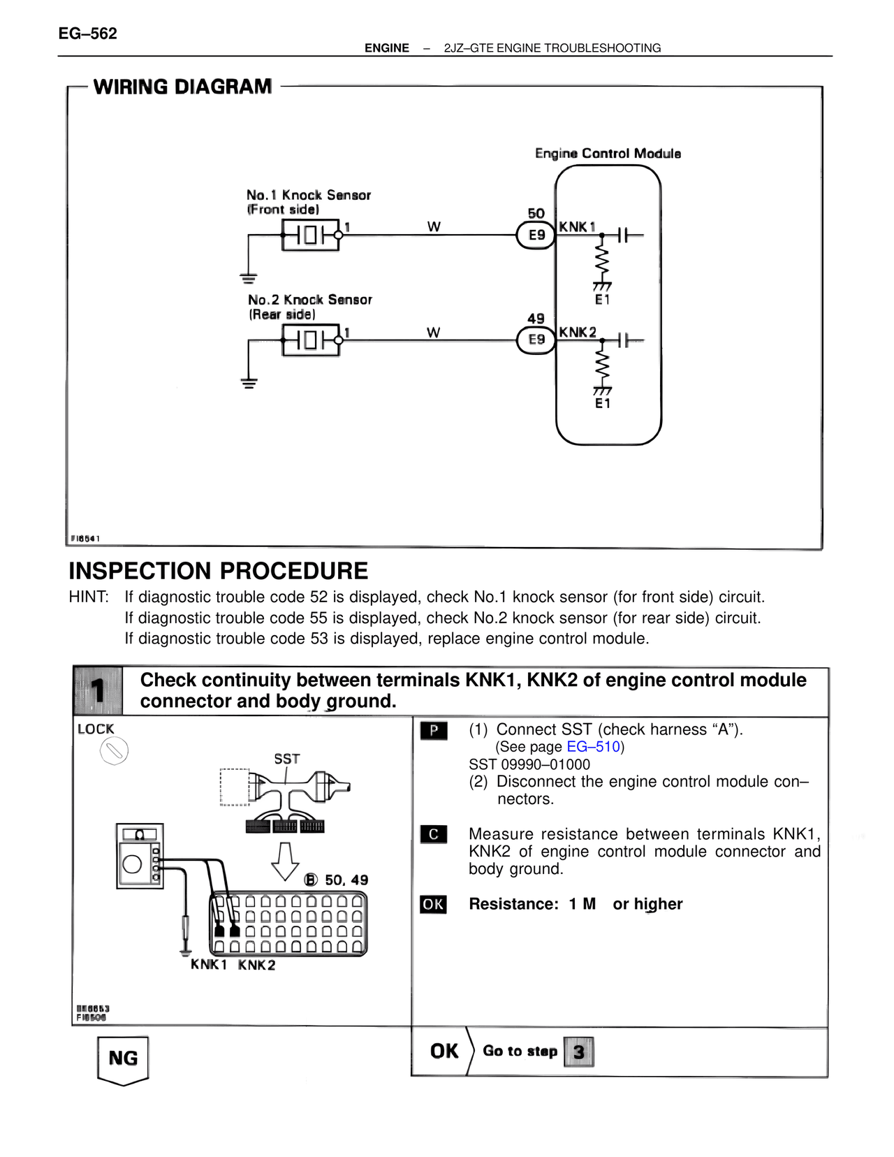
WIRING DIAGRAM

Engine Control Module

No.1 Knock Sensor
(Front side)
1     W     50  KNK1
E9
E1

No.2 Knock Sensor
(Rear side)
1     W     49  KNK2
E9
E1

FI6541

INSPECTION PROCEDURE

HINT:  If diagnostic trouble code 52 is displayed, check No.1 knock sensor (for front side) circuit.
       If diagnostic trouble code 55 is displayed, check No.2 knock sensor (for rear side) circuit.
       If diagnostic trouble code 53 is displayed, replace engine control module.

1   Check continuity between terminals KNK1, KNK2 of engine control module
    connector and body ground.

LOCK

SST

B: 50, 49

KNK1  KNK2

BE6653
FI6506

P  (1)  Connect SST (check harness "A").
       (See page EG–510)
       SST 09990–01000
   (2)  Disconnect the engine control module con–
       nectors.

C  Measure resistance between terminals KNK1,
   KNK2 of engine control module connector and
   body ground.

OK  Resistance:  1 M   or higher

NG                    OK   Go to step  3