100%
To Ignition SW
IG Terminal
Test Light
Fuse Case
Short A
SW 1
Short B
Disconnect
Disconnect
Light
Relay
Short C
Disconnect
SW 2
Solenoid
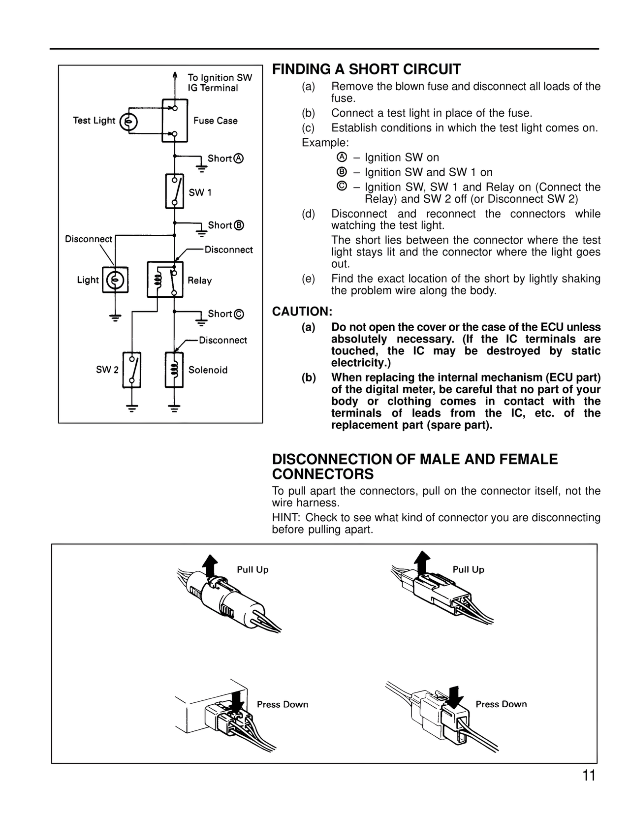
FINDING A SHORT CIRCUIT
(a) Remove the blown fuse and disconnect all loads of the fuse.
(b) Connect a test light in place of the fuse.
(c) Establish conditions in which the test light comes on.
Example:
A – Ignition SW on
B – Ignition SW and SW 1 on
C – Ignition SW, SW 1 and Relay on (Connect the Relay) and SW 2 off (or Disconnect SW 2)
(d) Disconnect and reconnect the connectors while watching the test light.
The short lies between the connector where the test light stays lit and the connector where the light goes out.
(e) Find the exact location of the short by lightly shaking the problem wire along the body.
CAUTION:
(a) Do not open the cover or the case of the ECU unless absolutely necessary. (If the IC terminals are touched, the IC may be destroyed by static electricity.)
(b) When replacing the internal mechanism (ECU part) of the digital meter, be careful that no part of your body or clothing comes in contact with the terminals of leads from the IC, etc. of the replacement part (spare part).
DISCONNECTION OF MALE AND FEMALE CONNECTORS
To pull apart the connectors, pull on the connector itself, not the wire harness.
HINT: Check to see what kind of connector you are disconnecting before pulling apart.
Pull Up
Pull Up
Press Down
Press Down
11