100%
Tool
Tab
Tab
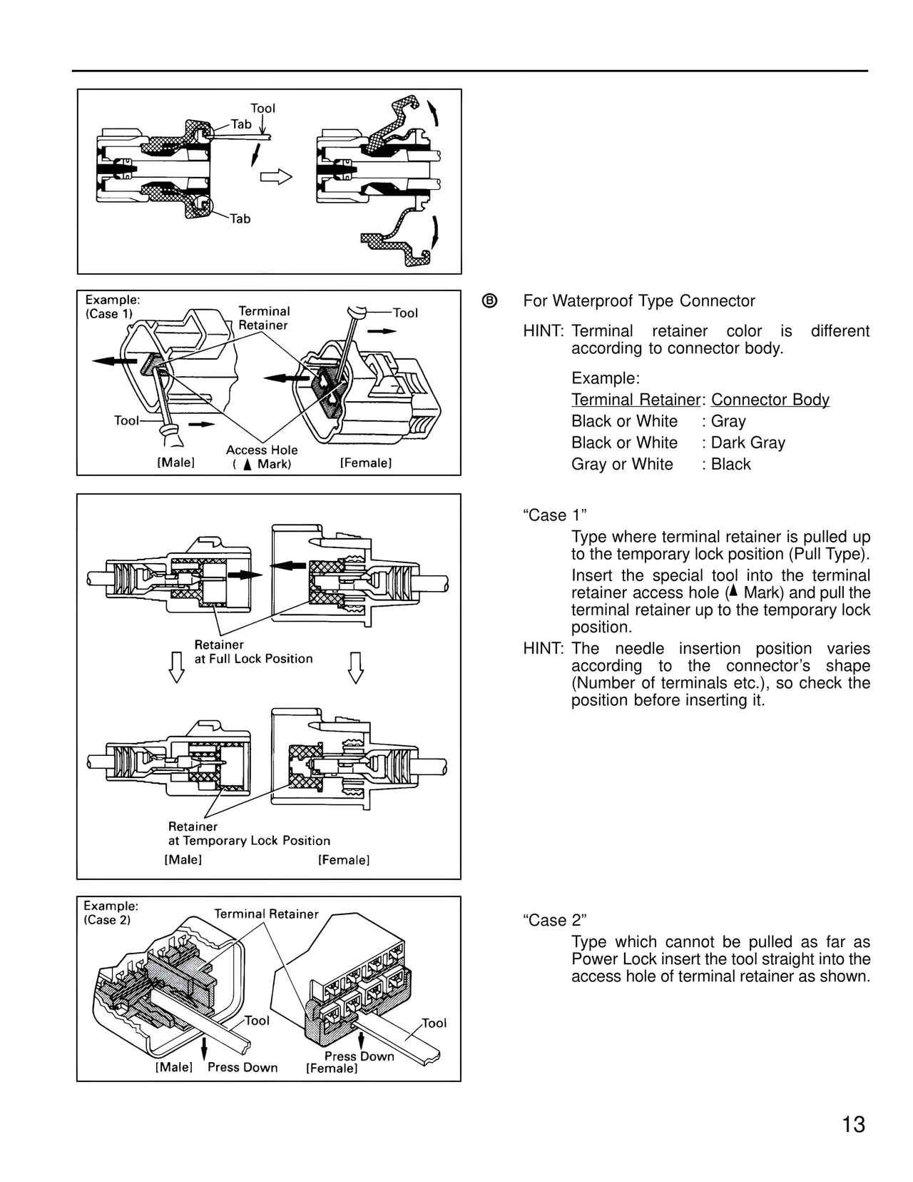
Example:
(Case 1)
Terminal
Retainer
Tool
Tool
Access Hole
( ▲ Mark)
[Male]
[Female]
Retainer
at Full Lock Position
Retainer
at Temporary Lock Position
[Male]
[Female]
Example:
(Case 2)
Terminal Retainer
Tool
Tool
[Male]
Press Down
Press Down
[Female]
ⓑ For Waterproof Type Connector
HINT: Terminal retainer color is different
according to connector body.
Example:
Terminal Retainer: Connector Body
Black or White : Gray
Black or White : Dark Gray
Gray or White : Black
"Case 1"
Type where terminal retainer is pulled up
to the temporary lock position (Pull Type).
Insert the special tool into the terminal
retainer access hole (▲ Mark) and pull the
terminal retainer up to the temporary lock
position.
HINT: The needle insertion position varies
according to the connector's shape
(Number of terminals etc.), so check the
position before inserting it.
"Case 2"
Type which cannot be pulled as far as
Power Lock insert the tool straight into the
access hole of terminal retainer as shown.
13