Page text (OCR transcript)
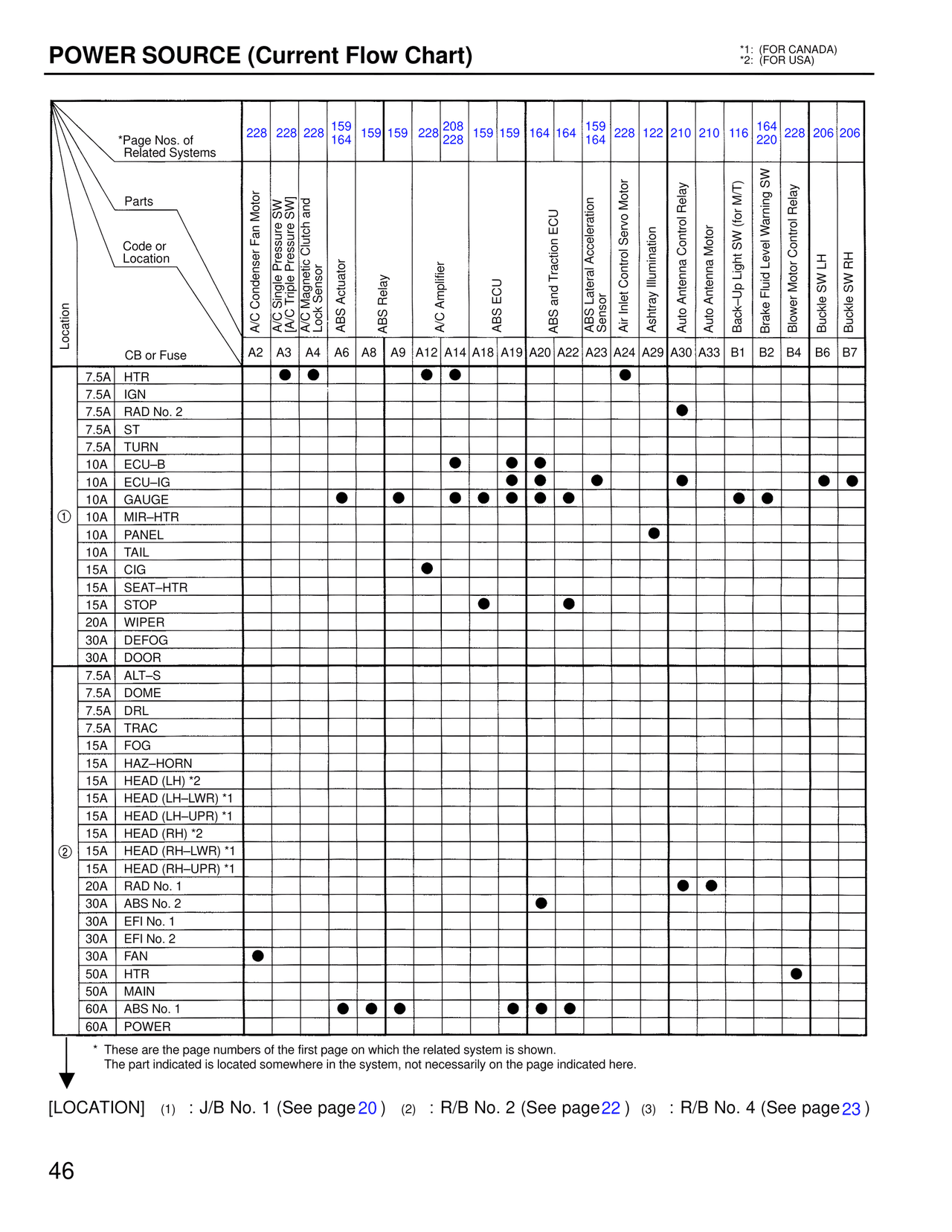
POWER SOURCE (Current Flow Chart)
*1: (FOR CANADA)
*2: (FOR USA)

*Page Nos. of Related Systems
228  228  228  159/164  159  159  228  208/228  159  159  164  164  159/164  228  122  210  210  116  164/220  228  206  206

Parts
Code or Location
Location
CB or Fuse

A/C Condenser Fan Motor  A2
A/C Single Pressure SW [A/C Triple Pressure SW]  A3
A/C Magnetic Clutch and Lock Sensor  A4
ABS Actuator  A6
ABS Relay  A8
A/C Amplifier  A9
ABS ECU  A12  A14
ABS and Traction ECU  A18  A19
ABS Lateral Acceleration Sensor  A20  A22
Air Inlet Control Servo Motor  A23
Ashtray Illumination  A24
Auto Antenna Control Relay  A29
Auto Antenna Motor  A30  A33
Back-Up Light SW (for M/T)  B1
Brake Fluid Level Warning SW  B2
Blower Motor Control Relay  B4
Buckle SW LH  B6
Buckle SW RH  B7

7.5A  HTR
7.5A  IGN
7.5A  RAD No. 2
7.5A  ST
7.5A  TURN
10A  ECU-B
10A  ECU-IG
10A  GAUGE
① 10A  MIR-HTR
10A  PANEL
10A  TAIL
15A  CIG
15A  SEAT-HTR
15A  STOP
20A  WIPER
30A  DEFOG
30A  DOOR
7.5A  ALT-S
7.5A  DOME
7.5A  DRL
7.5A  TRAC
15A  FOG
15A  HAZ-HORN
15A  HEAD (LH) *2
15A  HEAD (LH-LWR) *1
15A  HEAD (LH-UPR) *1
15A  HEAD (RH) *2
② 15A  HEAD (RH-LWR) *1
15A  HEAD (RH-UPR) *1
20A  RAD No. 1
30A  ABS No. 2
30A  EFI No. 1
30A  EFI No. 2
30A  FAN
50A  HTR
50A  MAIN
60A  ABS No. 1
60A  POWER

* These are the page numbers of the first page on which the related system is shown.
  The part indicated is located somewhere in the system, not necessarily on the page indicated here.

[LOCATION]  (1) : J/B No. 1 (See page 20)  (2) : R/B No. 2 (See page 22)  (3) : R/B No. 4 (See page 23)

46