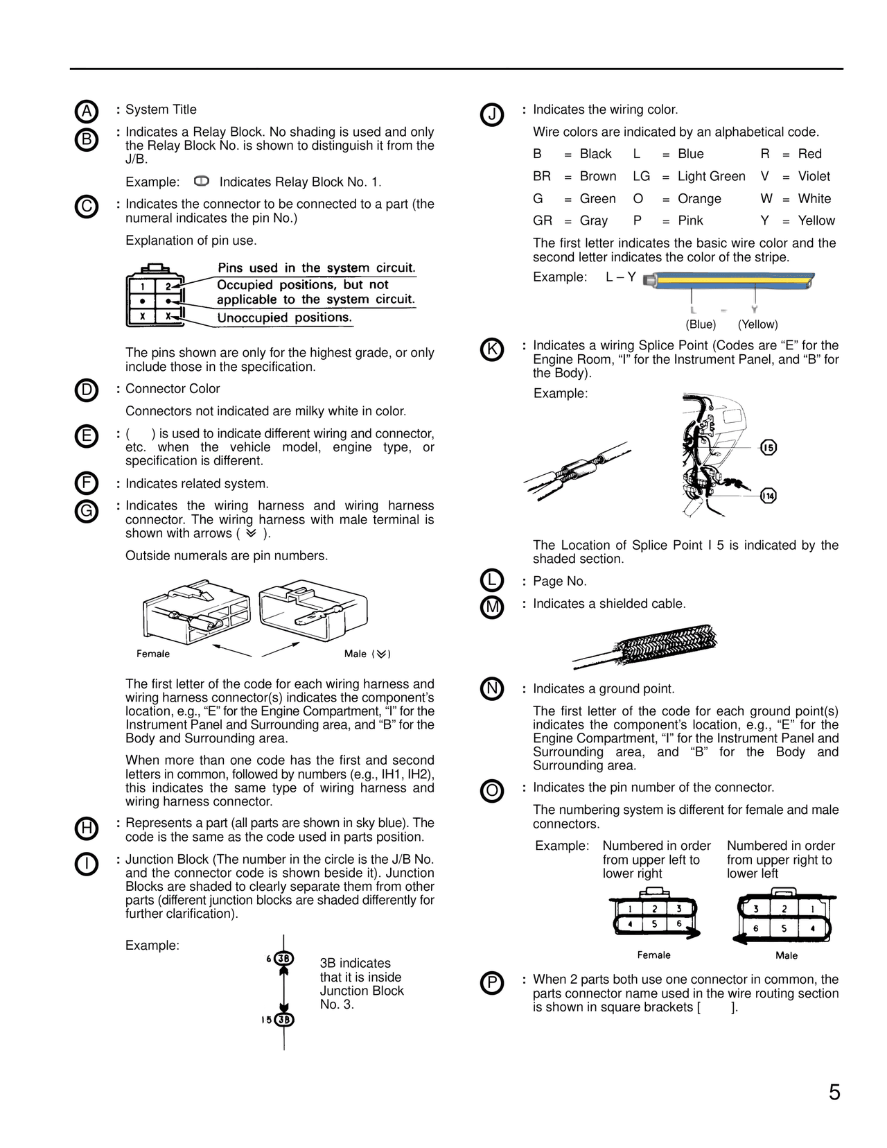
Page text (OCR transcript)
A : System Title

B : Indicates a Relay Block. No shading is used and only the Relay Block No. is shown to distinguish it from the J/B.

Example: [symbol] Indicates Relay Block No. 1.

C : Indicates the connector to be connected to a part (the numeral indicates the pin No.)

Explanation of pin use.

Pins used in the system circuit.
Occupied positions, but not applicable to the system circuit.
Unoccupied positions.

The pins shown are only for the highest grade, or only include those in the specification.

D : Connector Color

Connectors not indicated are milky white in color.

E : ( ) is used to indicate different wiring and connector, etc. when the vehicle model, engine type, or specification is different.

F : Indicates related system.

G : Indicates the wiring harness and wiring harness connector. The wiring harness with male terminal is shown with arrows ( [symbol] ).

Outside numerals are pin numbers.

Female                    Male ([symbol])

The first letter of the code for each wiring harness and wiring harness connector(s) indicates the component's location, e.g., "E" for the Engine Compartment, "I" for the Instrument Panel and Surrounding area, and "B" for the Body and Surrounding area.

When more than one code has the first and second letters in common, followed by numbers (e.g., IH1, IH2), this indicates the same type of wiring harness and wiring harness connector.

H : Represents a part (all parts are shown in sky blue). The code is the same as the code used in parts position.

I : Junction Block (The number in the circle is the J/B No. and the connector code is shown beside it). Junction Blocks are shaded to clearly separate them from other parts (different junction blocks are shaded differently for further clarification).

Example:

6 [3B]          3B indicates
                    that it is inside
                    Junction Block
                    No. 3.
I 5 [3B]

J : Indicates the wiring color.

Wire colors are indicated by an alphabetical code.

B  = Black    L  = Blue         R = Red
BR = Brown   LG = Light Green  V = Violet
G  = Green    O  = Orange       W = White
GR = Gray     P  = Pink         Y = Yellow

The first letter indicates the basic wire color and the second letter indicates the color of the stripe.

Example: L – Y [color swatch]
           (Blue)  (Yellow)

K : Indicates a wiring Splice Point (Codes are "E" for the Engine Room, "I" for the Instrument Panel, and "B" for the Body).

Example:

[diagram showing splice points I5 and I4]

The Location of Splice Point I 5 is indicated by the shaded section.

L : Page No.

M : Indicates a shielded cable.

[diagram of shielded cable]

N : Indicates a ground point.

The first letter of the code for each ground point(s) indicates the component's location, e.g., "E" for the Engine Compartment, "I" for the Instrument Panel and Surrounding area, and "B" for the Body and Surrounding area.

O : Indicates the pin number of the connector.

The numbering system is different for female and male connectors.

Example:   Numbered in order        Numbered in order
            from upper left to         from upper right to
            lower right                lower left

[diagram showing Female connector numbered 1,2,3 / 4,5,6]
[diagram showing Male connector numbered 3,2,1 / 6,5,4]

Female                              Male

P : When 2 parts both use one connector in common, the parts connector name used in the wire routing section is shown in square brackets [          ].

5