Page text (OCR transcript)
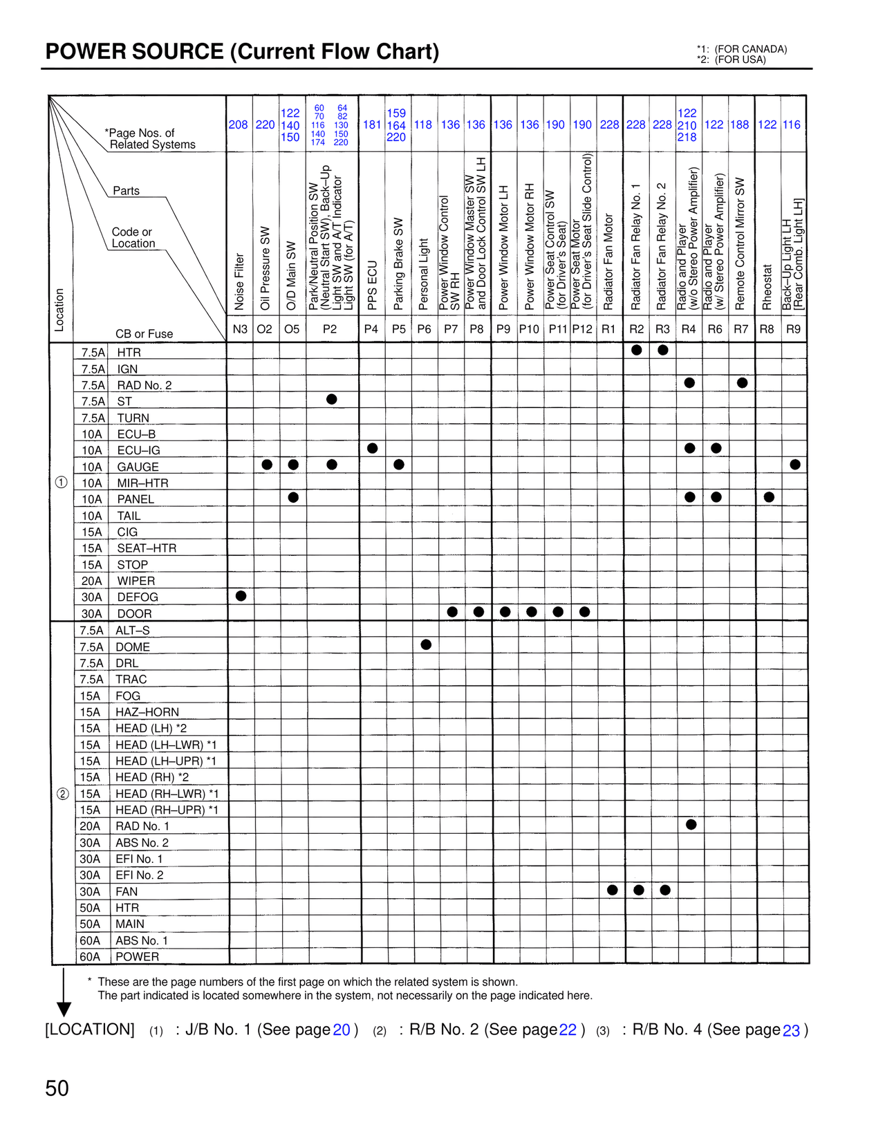
POWER SOURCE (Current Flow Chart)
*1: (FOR CANADA)
*2: (FOR USA)

*Page Nos. of Related Systems

Parts

Code or Location

Location

CB or Fuse

Page Numbers (top row):
208  220  122 140 150  60 70 116 140 174  64 82 130 150 220  181  159 164 220  118  136  136  136  136  190  190  228  228  228  122 210 218  122  188  122  116

Parts (column headers):
Noise Filter | Oil Pressure SW | O/D Main SW | Park/Neutral Position SW O/D Cancel SW and Up-Light SW and A/T Indicator Light SW (for A/T) | PPS ECU | Parking Brake SW | Personal Light | Power Window Control SW RH | Power Window Master SW and Door Lock Control SW LH | Power Window Motor LH | Power Window Motor RH | Power Seat Control SW (for Driver's Seat) | Power Seat Motor (for Driver's Seat Slide Control) | Radiator Fan Motor | Radiator Fan Relay No. 1 | Radiator Fan Relay No. 2 | Radio and Player (w/o Stereo Power Amplifier) | Radio and Player (w Stereo Power Amplifier) | Remote Control Mirror SW | Rheostat | Back-Up Light LH [Rear Comb. Light LH]

Code/Location:
N3  O2  O5  P2  P4  P5  P6  P7  P8  P9  P10  P11  P12  R1  R2  R3  R4  R6  R7  R8  R9

① (J/B No. 1)
7.5A  HTR         ●  ●
7.5A  IGN
7.5A  RAD No. 2                                              ●        ●
7.5A  ST          ●
7.5A  TURN
10A   ECU-B
10A   ECU-IG                    ●                                    ●  ●
10A   GAUGE    ●  ●   ●           ●
10A   MIR-HTR
10A   PANEL        ●                                              ●  ●     ●
10A   TAIL
15A   CIG
15A   SEAT-HTR
15A   STOP
20A   WIPER
30A   DEFOG  ●
30A   DOOR                          ●  ●  ●  ●  ●  ●

② (R/B No. 2)
7.5A  ALT-S
7.5A  DOME                   ●
7.5A  DRL
7.5A  TRAC
15A   FOG
15A   HAZ-HORN
15A   HEAD (LH) *2
15A   HEAD (LH-LWR) *1
15A   HEAD (LH-UPR) *1
15A   HEAD (RH) *2
15A   HEAD (RH-LWR) *1
15A   HEAD (RH-UPR) *1
20A   RAD No. 1                                                   ●
30A   ABS No. 2
30A   EFI No. 1
30A   EFI No. 2
30A   FAN                                            ●  ●  ●
50A   HTR
50A   MAIN
60A   ABS No. 1
60A   POWER

* These are the page numbers of the first page on which the related system is shown.
  The part indicated is located somewhere in the system, not necessarily on the page indicated here.

[LOCATION]  (1) : J/B No. 1 (See page 20)   (2) : R/B No. 2 (See page 22)   (3) : R/B No. 4 (See page 23)

50