AT-74 AUTOMATIC TRANSMISSION — Component Groups (Center Support Assembly)
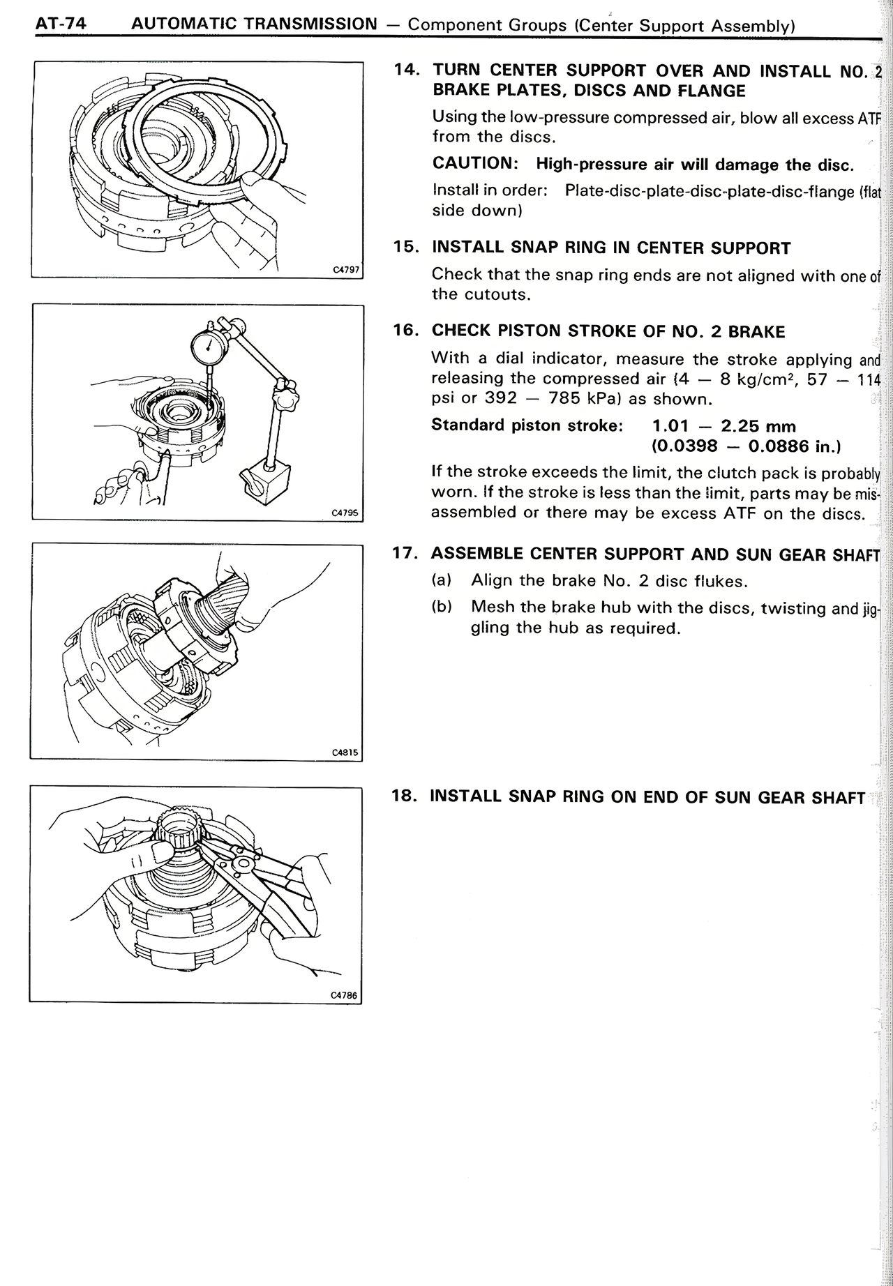
14. TURN CENTER SUPPORT OVER AND INSTALL NO. 2 BRAKE PLATES, DISCS AND FLANGE
Using the low-pressure compressed air, blow all excess ATF from the discs.
CAUTION: High-pressure air will damage the disc.
Sequence: Plate-disc-plate-disc-plate-disc-plate-disc-flange (flat side down)
15. INSTALL SNAP RING IN CENTER SUPPORT
Check that the snap ring ends are not aligned with one of the cutouts.
16. CHECK PISTON STROKE OF NO. 2 BRAKE
With a dial indicator, measure the stroke applying and releasing the compressed air (4 — 8 kg/cm², 57 — 114 psi or 392 — 785 kPa) as shown.
Standard piston stroke: 1.01 — 2.25 mm
(0.0398 — 0.0886 in.)
If the stroke exceeds the limit, the clutch pack is probably worn. If the stroke is less than the limit, parts may be misassembled or there may be excess ATF on the discs.
17. ASSEMBLE CENTER SUPPORT AND SUN GEAR SHAFT
(a) Align the brake No. 2 disc flukes.
(b) Mesh the brake hub with the discs, twisting and jiggling the hub as required.
18. INSTALL SNAP RING ON END OF SUN GEAR SHAFT