BE-82
BODY ELECTRICAL SYSTEM — Cruise Control System
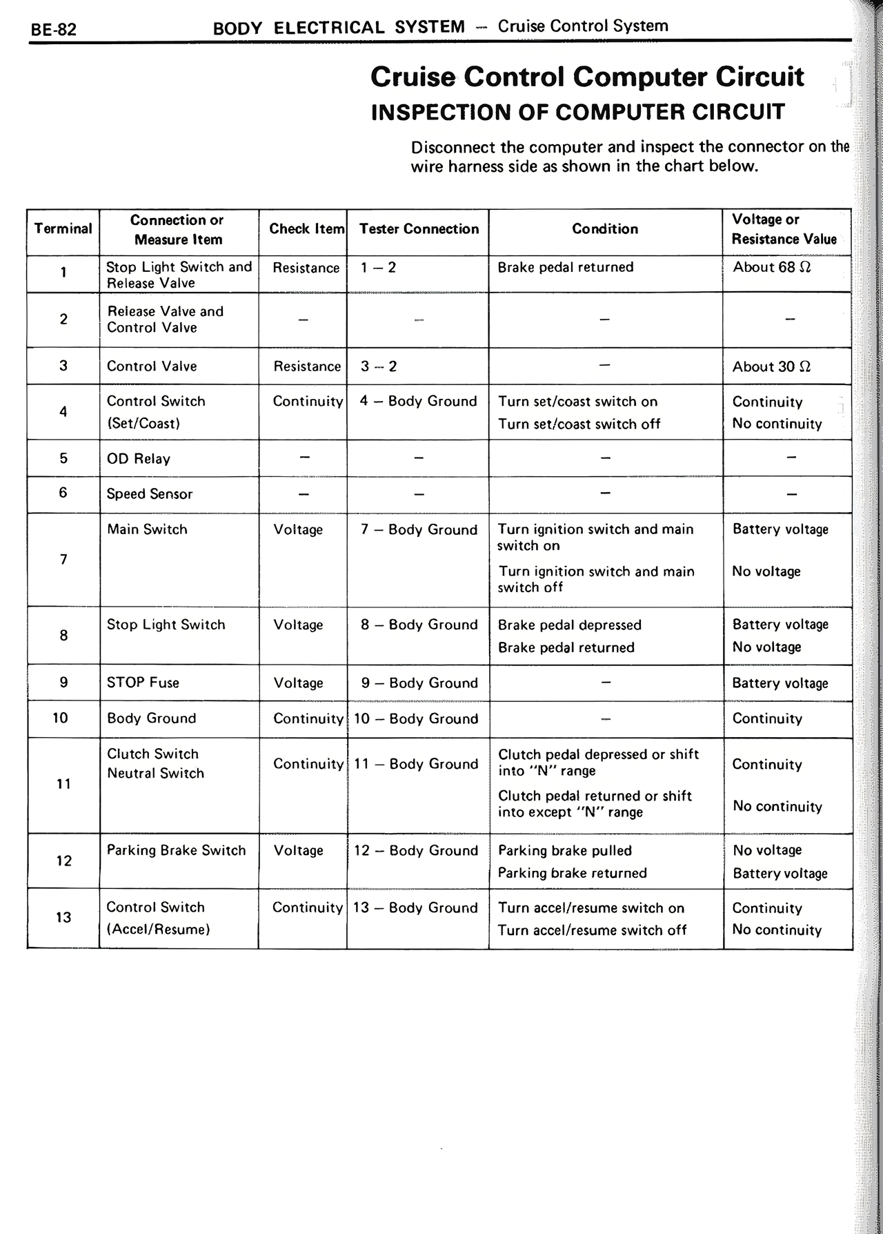
Cruise Control Computer Circuit
INSPECTION OF COMPUTER CIRCUIT
Disconnect the computer and inspect the connector on the
wire harness side as shown in the chart below.
Terminal | Connection or Measure Item | Check Item | Tester Connection | Condition | Voltage or Resistance Value
1 | Stop Light Switch and Release Valve | Resistance | 1 — 2 | Brake pedal returned | About 68 Ω
2 | Release Valve and Control Valve | — | — | — | —
3 | Control Valve | Resistance | 3 — 2 | — | About 30 Ω
4 | Control Switch (Set/Coast) | Continuity | 4 — Body Ground | Turn set/coast switch on
Turn set/coast switch off | Continuity
No continuity
5 | OD Relay | — | — | — | —
6 | Speed Sensor | — | — | — | —
7 | Main Switch | Voltage | 7 — Body Ground | Turn ignition switch and main switch on
Turn ignition switch and main switch off | Battery voltage
No voltage
8 | Stop Light Switch | Voltage | 8 — Body Ground | Brake pedal depressed
Brake pedal returned | Battery voltage
No voltage
9 | STOP Fuse | Voltage | 9 — Body Ground | — | Battery voltage
10 | Body Ground | Continuity | 10 — Body Ground | — | Continuity
11 | Clutch Switch
Neutral Switch | Continuity | 11 — Body Ground | Clutch pedal depressed or shift into "N" range
Clutch pedal returned or shift into except "N" range | Continuity
No continuity
12 | Parking Brake Switch | Voltage | 12 — Body Ground | Parking brake pulled
Parking brake returned | No voltage
Battery voltage
13 | Control Switch (Accel/Resume) | Continuity | 13 — Body Ground | Turn accel/resume switch on
Turn accel/resume switch off | Continuity
No continuity