EM-26
ENGINE MECHANICAL — Cylinder Head
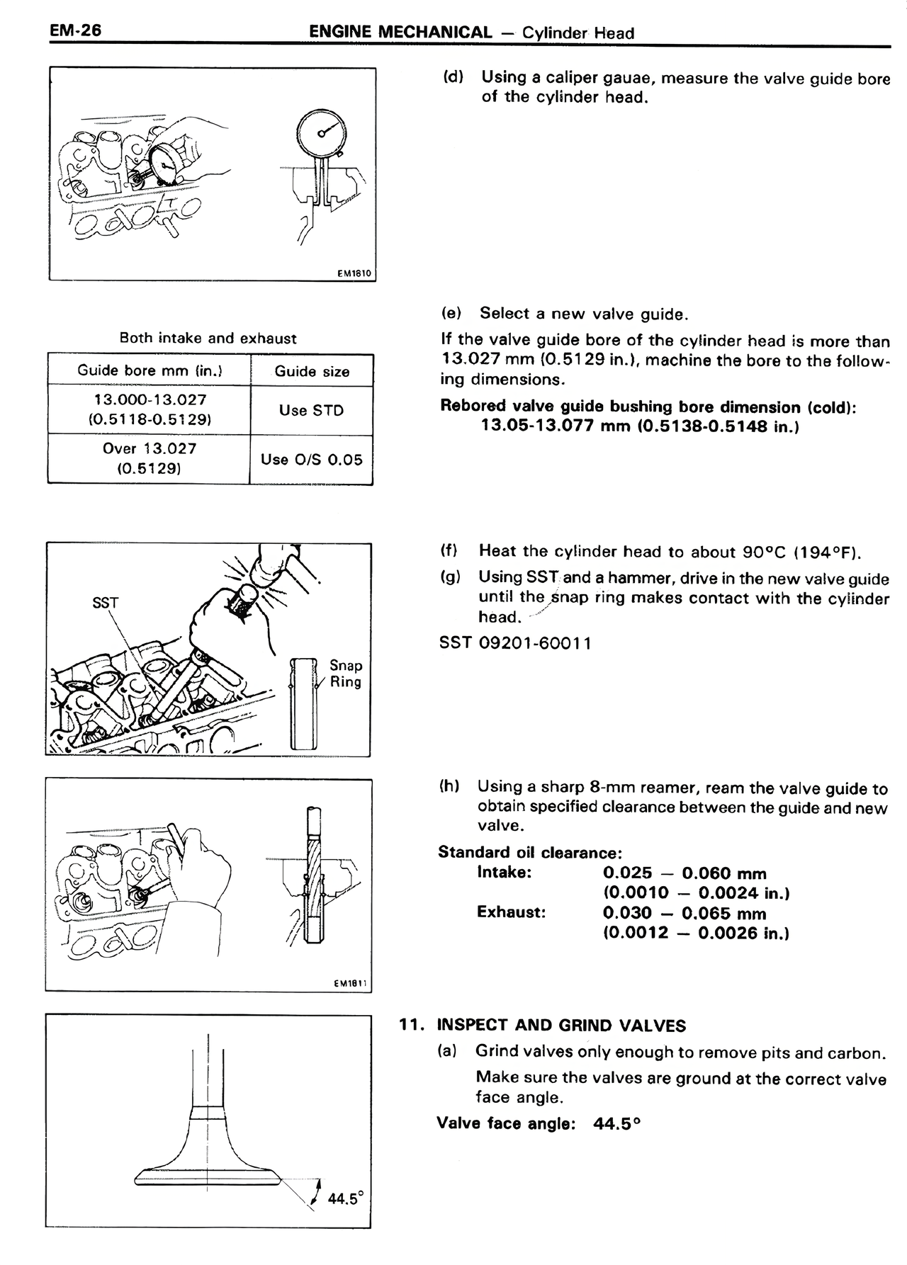
(d) Using a caliper gauge, measure the valve guide bore of the cylinder head.
Both intake and exhaust
Guide bore mm (in.) | Guide size
13.000-13.027 | Use STD
(0.5118-0.5129)
Over 13.027 | Use O/S 0.05
(0.5129)
(e) Select a new valve guide.
If the valve guide bore of the cylinder head is more than 13.027 mm (0.5129 in.), machine the bore to the following dimensions.
Rebored valve guide bushing bore dimension (cold):
13.05-13.077 mm (0.5138-0.5148 in.)
(f) Heat the cylinder head to about 90°C (194°F).
(g) Using SST and a hammer, drive in the new valve guide until the snap ring makes contact with the cylinder head.
SST 09201-60011
(h) Using a sharp 8-mm reamer, ream the valve guide to obtain specified clearance between the guide and new valve.
Standard oil clearance:
Intake: 0.025 — 0.060 mm
(0.0010 — 0.0024 in.)
Exhaust: 0.030 — 0.068 mm
(0.0012 — 0.0028 in.)
11. INSPECT AND GRIND VALVES
(a) Grind valves only enough to remove pits and carbon. Make sure the valves are ground at the correct valve face angle.
Valve face angle: 44.5°