EM-58 ENGINE MECHANICAL — Cylinder Block
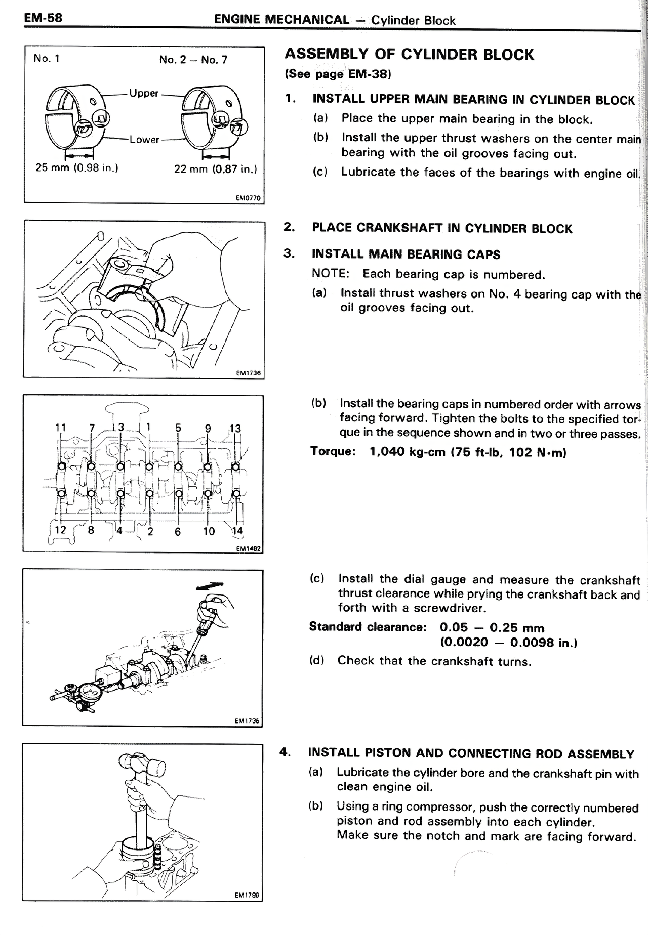
No. 1 No. 2 — No. 7
[DIAGRAM: Shows upper and lower main bearings with measurements - 25 mm (0.98 in.) for No. 1 and 22 mm (0.87 in.) for No. 2-7]
EM0078
[DIAGRAM: Hands installing crankshaft in cylinder block]
EM0135
[DIAGRAM: Numbered bearing cap installation sequence showing positions 1-14]
EM1487
[DIAGRAM: Using dial gauge to measure crankshaft thrust clearance]
EM1735
[DIAGRAM: Installing piston and connecting rod assembly]
EM1705
ASSEMBLY OF CYLINDER BLOCK
(See page EM-38)
1. INSTALL UPPER MAIN BEARING IN CYLINDER BLOCK
(a) Place the upper main bearing in the block.
(b) Install the upper thrust washers on the center main bearing with the oil grooves facing out.
(c) Lubricate the faces of the bearings with engine oil.
2. PLACE CRANKSHAFT IN CYLINDER BLOCK
3. INSTALL MAIN BEARING CAPS
NOTE: Each bearing cap is numbered.
(a) Install thrust washers on No. 4 bearing cap with the oil grooves facing out.
(b) Install the bearing caps in numbered order with arrows facing forward. Tighten the bolts to the specified torque in the sequence shown and in two or three passes.
Torque: 1,040 kg-cm (75 ft-lb, 102 N-m)
(c) Install the dial gauge and measure the crankshaft thrust clearance while prying the crankshaft back and forth with a screwdriver.
Standard clearance: 0.05 — 0.25 mm
(0.0020 — 0.0098 in.)
(d) Check that the crankshaft turns.
4. INSTALL PISTON AND CONNECTING ROD ASSEMBLY
(a) Lubricate the cylinder bore and the crankshaft pin with clean engine oil.
(b) Using a ring compressor, push the correctly numbered piston and rod assembly into each cylinder. Make sure the notch and mark are facing forward.