LU-6
LUBRICATION SYSTEM — Oil Pump
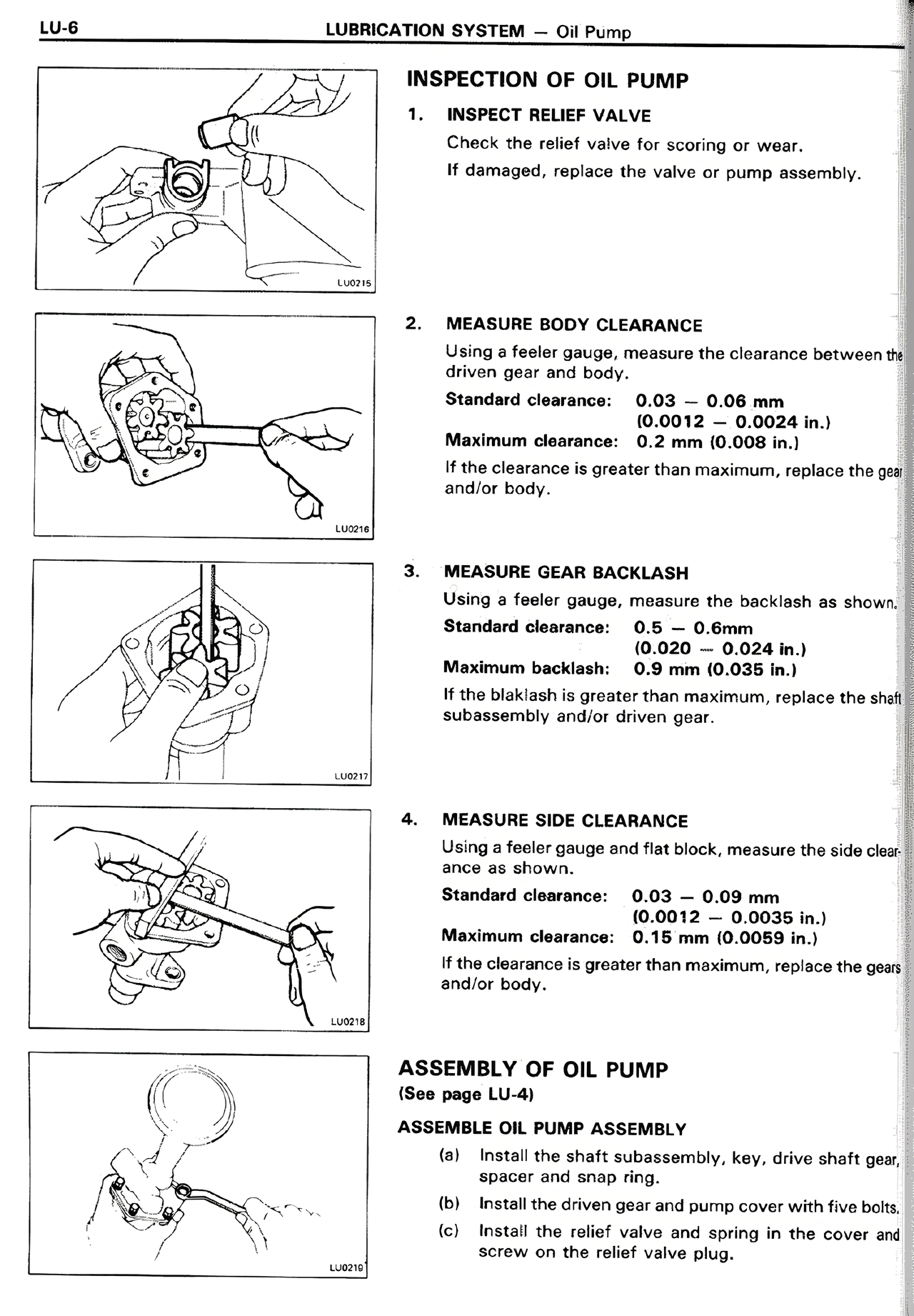
INSPECTION OF OIL PUMP
1. INSPECT RELIEF VALVE
Check the relief valve for scoring or wear.
If damaged, replace the valve or pump assembly.
2. MEASURE BODY CLEARANCE
Using a feeler gauge, measure the clearance between the
driven gear and body.
Standard clearance: 0.03 - 0.08 mm
(0.0012 - 0.0024 in.)
Maximum clearance: 0.2 mm (0.008 in.)
If the clearance is greater than maximum, replace the gear
and/or body.
3. MEASURE GEAR BACKLASH
Using a feeler gauge, measure the backlash as shown.
Standard clearance: 0.5 - 0.8mm
(0.020 - 0.024 in.)
Maximum backlash: 0.9 mm (0.035 in.)
If the blaklash is greater than maximum, replace the shaft
subassembly and/or driven gear.
4. MEASURE SIDE CLEARANCE
Using a feeler gauge and flat block, measure the side clearance as shown.
Standard clearance: 0.03 - 0.09 mm
(0.0012 - 0.0035 in.)
Maximum clearance: 0.15 mm (0.0059 in.)
If the clearance is greater than maximum, replace the gears
and/or body.
ASSEMBLY OF OIL PUMP
(See page LU-4)
ASSEMBLE OIL PUMP ASSEMBLY
(a) Fit the shaft subassembly, key, drive shaft gear, drive
spacer and snap ring.
(b) Install the driven gear and pump cover with five bolts.
(c) Install the relief valve and spring in the cover and
screw on the relief valve plug.