100%
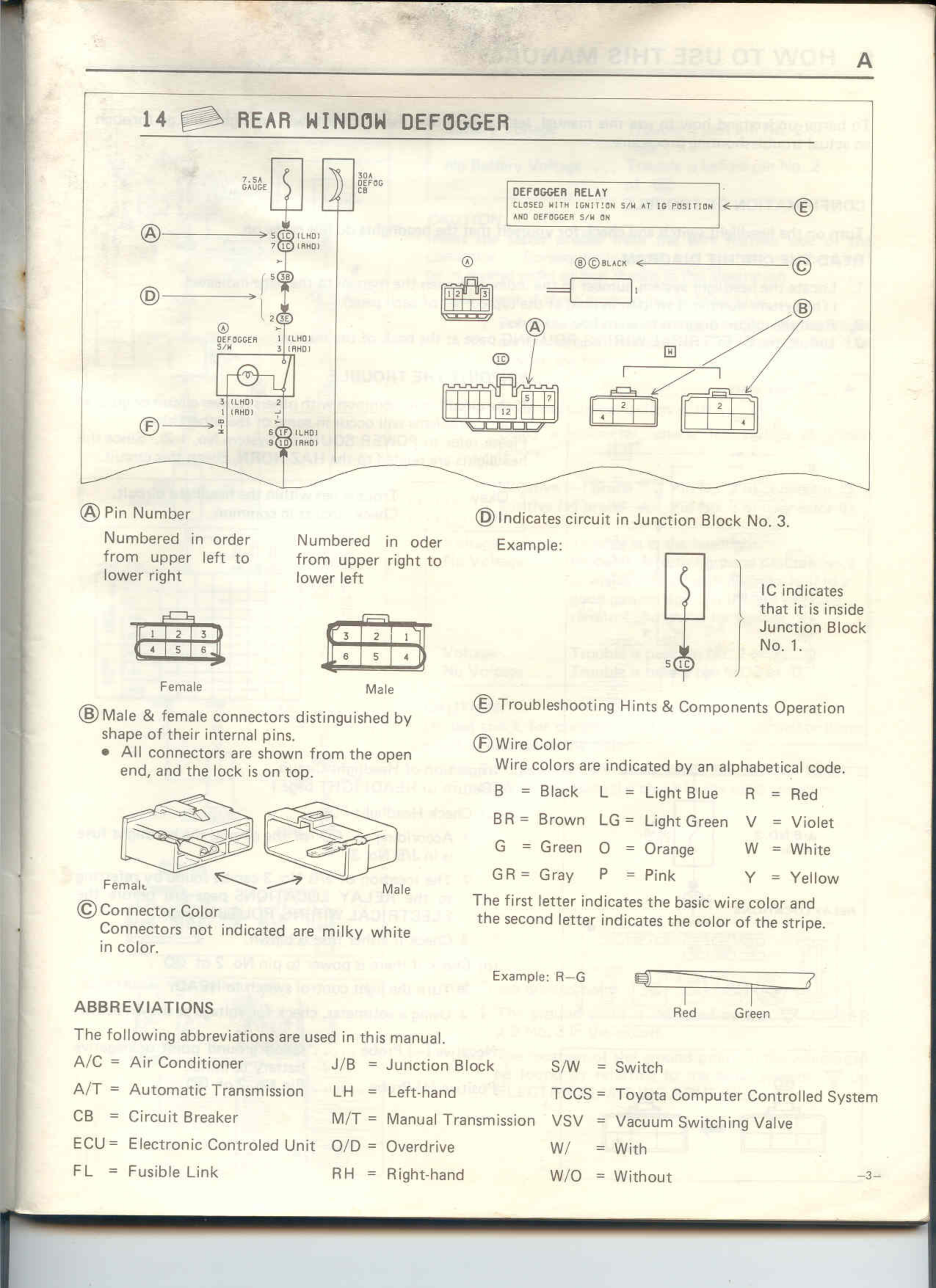
14 REAR WINDOW DEFOGGER
FUSE GAGE
RELAY DEF&IG
DEFOGGER RELAY
CLOSED WITH IGNITION S/W AT IG POSITION
AND DEFOGGER S/W ON
E
B/O BLACK
C
A
B
DEFOGGER
F
A Pin Number
Numbered in order
from upper left to
lower right
Numbered in order
from upper right to
lower left
D Indicates circuit in Junction Block No. 3.
Example:
IC indicates
that it is inside
Junction Block
No. 1.
Female
Male
B Male & female connectors distinguished by
shape of their internal pins.
• All connectors are shown from the open
end, and the lock is on top.
E Troubleshooting Hints & Components Operation
F Wire Color
Wire colors are indicated by an alphabetical code.
B = Black L = Light Blue R = Red
BR = Brown LG = Light Green V = Violet
G = Green O = Orange W = White
GR = Gray P = Pink Y = Yellow
The first letter indicates the basic wire color and
the second letter indicates the color of the stripe.
Female
Male
C Connector Color
Connectors not indicated are milky white
in color.
Example: R-G
Red Green
ABBREVIATIONS
The following abbreviations are used in this manual.
A/C = Air Conditioner
A/T = Automatic Transmission
CB = Circuit Breaker
ECU = Electronic Controlled Unit
FL = Fusible Link
J/B = Junction Block
LH = Left-hand
M/T = Manual Transmission
O/D = Overdrive
RH = Right-hand
S/W = Switch
TCCS = Toyota Computer Controlled System
VSV = Vacuum Switching Valve
W/ = With
W/O = Without