100%
28-1
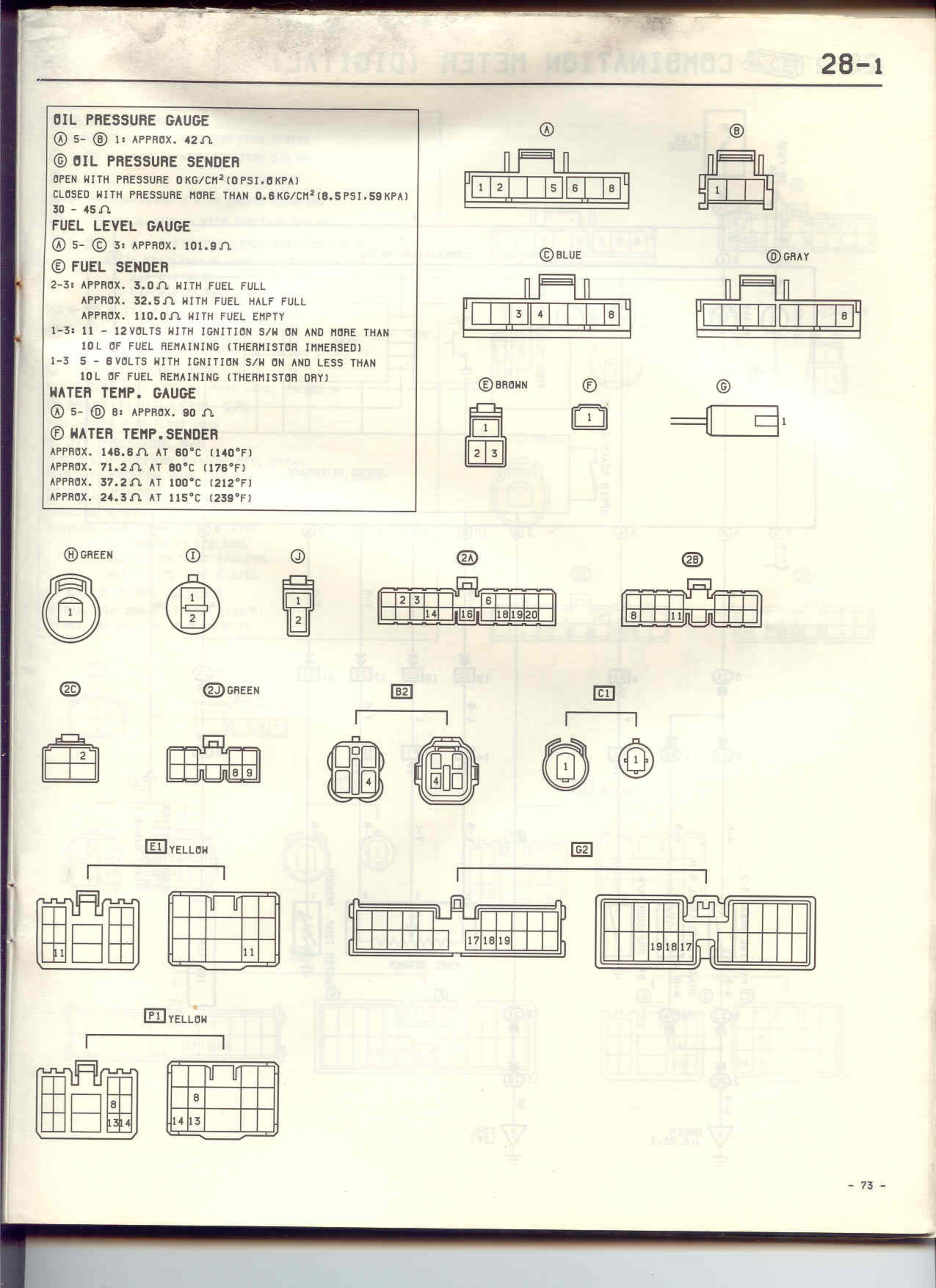
OIL PRESSURE GAUGE
① 5~ ⑧ 1: APPROX. 42Ω
⑦ OIL PRESSURE SENDER
OPEN WITH PRESSURE 0KG/CM²(0PSI,0KPA)
CLOSED WITH PRESSURE MORE THAN 0.6KG/CM²(8.5PSI,59KPA)
30 ~ 45Ω
FUEL LEVEL GAUGE
① 5~ ⑤ 3: APPROX. 101.8Ω
⑤ FUEL SENDER
2~3: APPROX. 3.0Ω WITH FUEL FULL
APPROX. 32.5Ω WITH FUEL HALF FULL
APPROX. 110.0Ω WITH FUEL EMPTY
1~3: 11 ~ 12VOLTS WITH IGNITION S/W ON AND MORE THAN
10L OF FUEL REMAINING (THERMISTOR IMMERSED)
1~3: 5 ~ 8VOLTS WITH IGNITION S/W ON AND LESS THAN
10L OF FUEL REMAINING (THERMISTOR DRY)
WATER TEMP. GAUGE
① 5~ ⑥ 8: APPROX. 90Ω
⑥ WATER TEMP.SENDER
APPROX. 148.8Ω AT 60°C (140°F)
APPROX. 71.2Ω AT 80°C (176°F)
APPROX. 37.2Ω AT 100°C (212°F)
APPROX. 24.3Ω AT 115°C (239°F)
①
[Connector diagram with pins 1, 2, 5, 6, 8]
⑧
[Connector diagram with pins 1, 8]
⑤BLUE
[Connector diagram with pins 1, 3, 4, 8]
⑥GRAY
[Connector diagram with pins 1-8]
⑤BROWN
[Connector diagram with pins 1, 2, 3]
⑦
[Single pin connector]
⑥
[Rectangular connector]
⑧GREEN
[Circular connector with pins 1, 2]
⑦
[Circular connector with pins 1, 2]
⑨
[Connector with pin 2]
②A
[Connector diagram with numbered pins 1-20]
②B
[Connector diagram with numbered pins]
②C
[2-pin connector]
②D GREEN
[Multi-pin connector diagram]
B2
[Connector diagrams showing circular and multi-pin configurations]
C1
[Circular connector diagrams]
E1 YELLOW
[Multiple connector diagrams showing pin layouts]
G2
[Connector diagrams with pins 17, 18, 19 and 19, 20, 17]
F1 YELLOW
[Connector diagrams with numbered pins including 8, 3, 4, 5]
- 73 -