100%
C TROUBLESHOOTING
TROUBLESHOOTING PROCEDURE
1. Determine what is wrong with the system.
2. First read the diagram so you understand the system. Refer to the component operation boxed within the system circuit.
3. Locate the cause of the problem.
a. Determine whether the problem is with the common circuit (power source or ground) or individual circuit.
Check other loads or switches which are in parallel with the problem component.
If they are normal, the problem lies within the particular system itself.
Refer to the POWER SOURCE or GROUND POINTS and check the related systems.
(NOTE: Each component is grounded at 2 or 3 points.)
If the related systems are normal, the common circuit (power source or ground points) is okay.
The problem lies within the individual system.
b. Locate the exact point of the problem by narrowing down the area with a voltmeter or test lamp.
4. Repair and re-check the circuit.
If any wiring was disconnected for troubleshooting, reconnect it and check the related circuits.
VOLTAGE CHECK
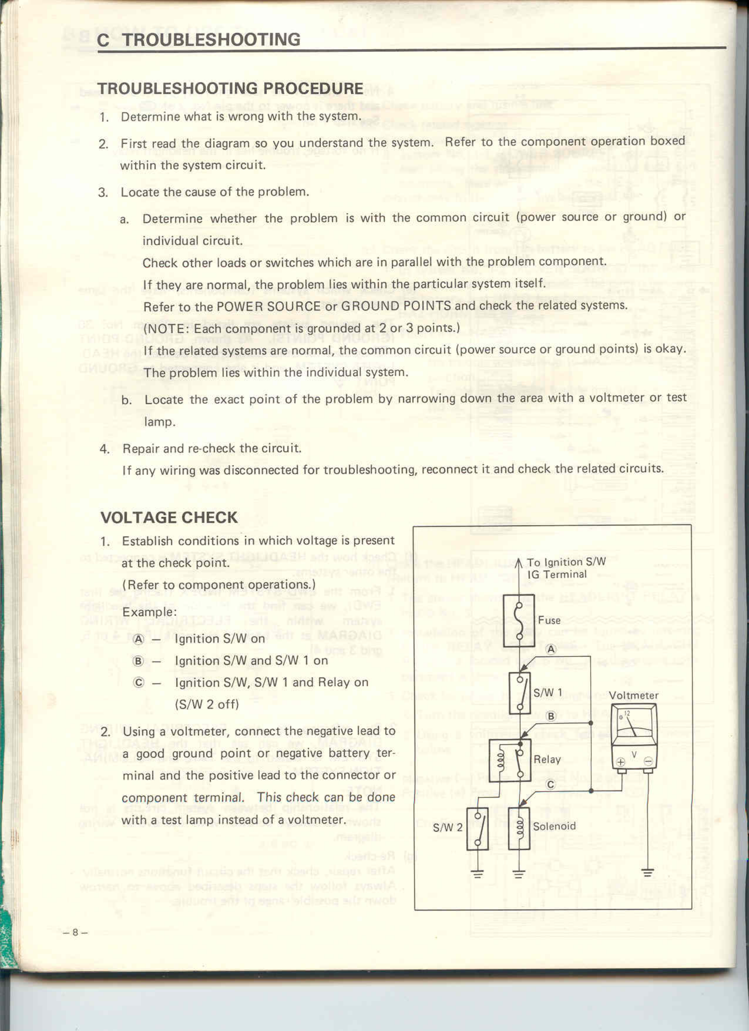
1. Establish conditions in which voltage is present at the check point.
(Refer to component operations.)
Example:
A - Ignition S/W on
B - Ignition S/W and S/W 1 on
C - Ignition S/W, S/W 1 and Relay on (S/W 2 off)
2. Using a voltmeter, connect the negative lead to a good ground point or negative battery terminal and the positive lead to the connector or component terminal. This check can be done with a test lamp instead of a voltmeter.
[DIAGRAM showing circuit with: To Ignition S/W IG Terminal, Fuse, S/W 1, Relay, Solenoid, S/W 2, Voltmeter, with points A, B, C marked and ground symbols]
-8-