100%
BODY ELECTRICAL SYSTEM — Trip Computer BE-117
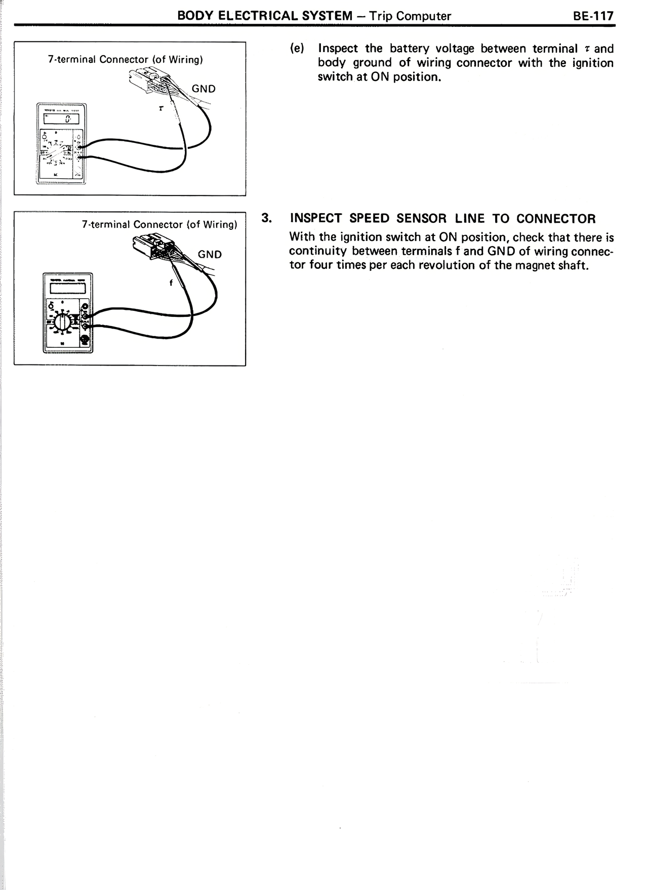
7-terminal Connector (of Wiring)
[Diagram showing connector with terminals marked GND, r, +]
(e) Inspect the battery voltage between terminal r and body ground of wiring connector with the ignition switch at ON position.
7-terminal Connector (of Wiring)
[Diagram showing connector with terminals marked GND, f, +]
3. INSPECT SPEED SENSOR LINE TO CONNECTOR
With the ignition switch at ON position, check that there is continuity between terminals f and GND of wiring connector four times per each revolution of the magnet shaft.