← p.032p.034 →
BE/Body Electrical System — Combination Meter and Gauge (Digital Type), page 33
33 / 121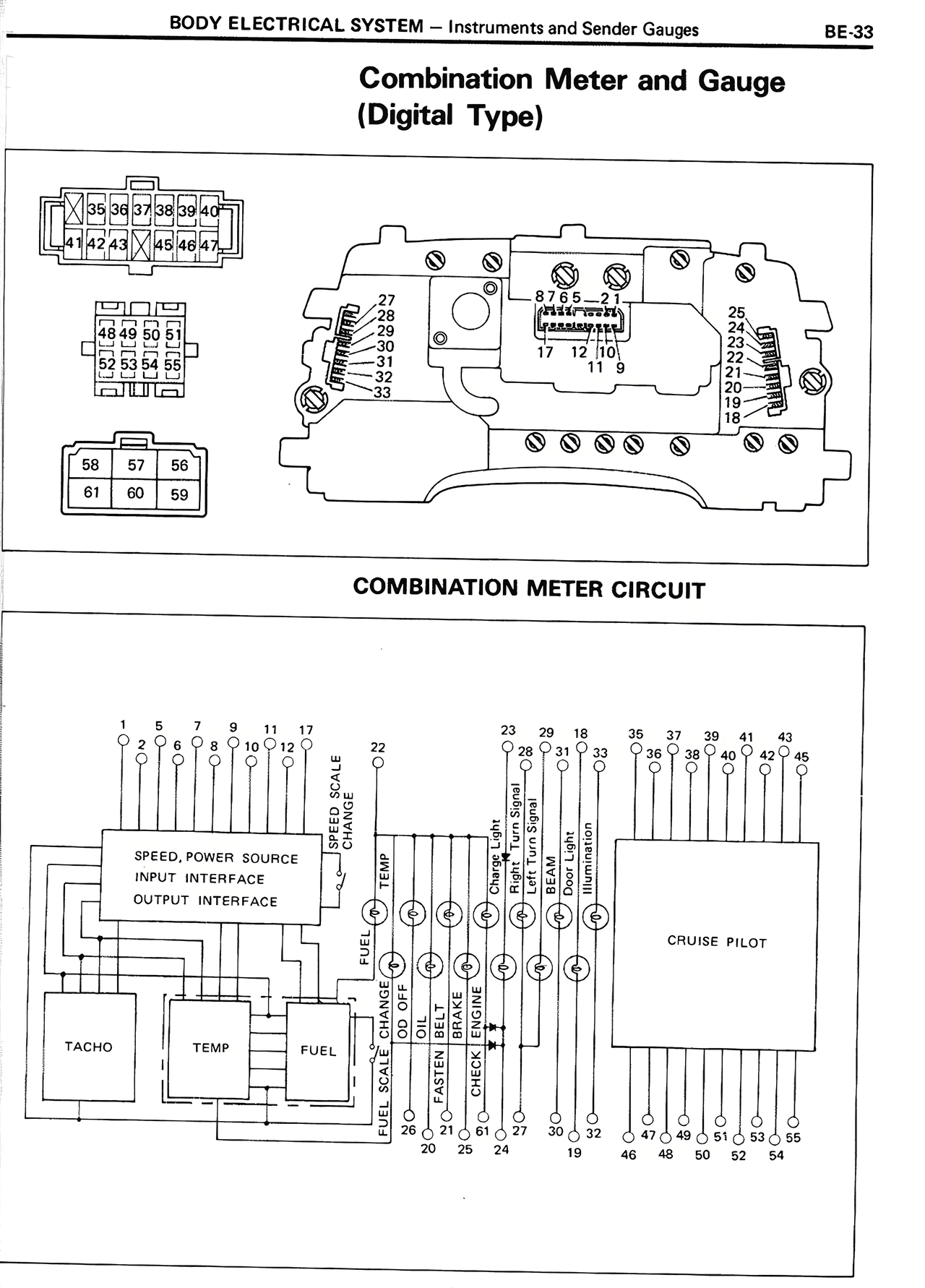
100%
Page text (OCR transcript)
BODY ELECTRICAL SYSTEM — Instruments and Sender Gauges                    BE-33

Combination Meter and Gauge
(Digital Type)

[Diagram showing combination meter circuit with numbered terminals and connections]

COMBINATION METER CIRCUIT

[Circuit diagram showing connections between various components including:
- Terminal numbers: 1, 2, 6, 7, 8, 9, 10, 12, 9
- SPEED, POWER SOURCE INPUT INTERFACE OUTPUT INTERFACE
- TACHO
- TEMP
- FUEL
- CRUISE PILOT
- Terminal numbers on right side: 23, 29, 18, 35, 37, 39, 41, 43
- Terminal numbers at bottom: 22, 20, 25, 24, 61, 27, 30, 32, 19, 47, 49, 46, 48, 50, 51, 52, 54, 55
- Labels including: METER SCALE CHARGE, L/IC, OIL FUEL, PARK SEL, PATTERN FRONT, OPTION, BELT, LIGHT]