100%
Fuel Gauge
INSPECTION OF FUEL GAUGE
1. INSPECT RECEIVER GAUGE OPERATION
Disconnect the connector from the fuel sender gauge.
2. INSPECT POWER SOURCE LINE TO CONNECTOR
Inspect the power source line between terminal FV and body ground of the sender gauge connector.
Voltage: 4.0 – 6.0V
CAUTION: Never short circuit terminal FV.
3. INSPECT OUTPUT SIGNAL VOLTAGE
Inspect the output signal voltage between terminal FR and body ground of the sender gauge connector.
Voltage: 4.4 – 4.8V at F level
3.27V at 1/2 level
2.3 – 2.7V at 1/4 level
0.3 – 0.5V at E level
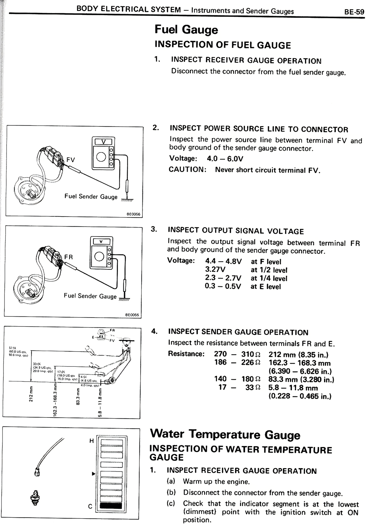
4. INSPECT SENDER GAUGE OPERATION
Inspect the resistance between terminals FR and E.
Resistance: 270 – 310Ω 212 mm (8.35 in.)
186 – 226Ω 162.3 mm (6.39 in.)
(6.390 – 6.626 in.)
140 – 180Ω 83.5 mm (3.280 in.)
17 – 33Ω 5.8 – 11.8 mm
(0.228 – 0.465 in.)
Water Temperature Gauge
INSPECTION OF WATER TEMPERATURE GAUGE
1. INSPECT RECEIVER GAUGE OPERATION
(a) Warm up the engine.
(b) Disconnect the connector from the sender gauge.
(c) Check that the indicator segment is at the lowest (dimmest) point with the ignition switch at ON position.