100%
BE-84 BODY ELECTRICAL SYSTEM - Cruise Control System
Stop Light Switch
INSPECTION OF STOP LIGHT SWITCH
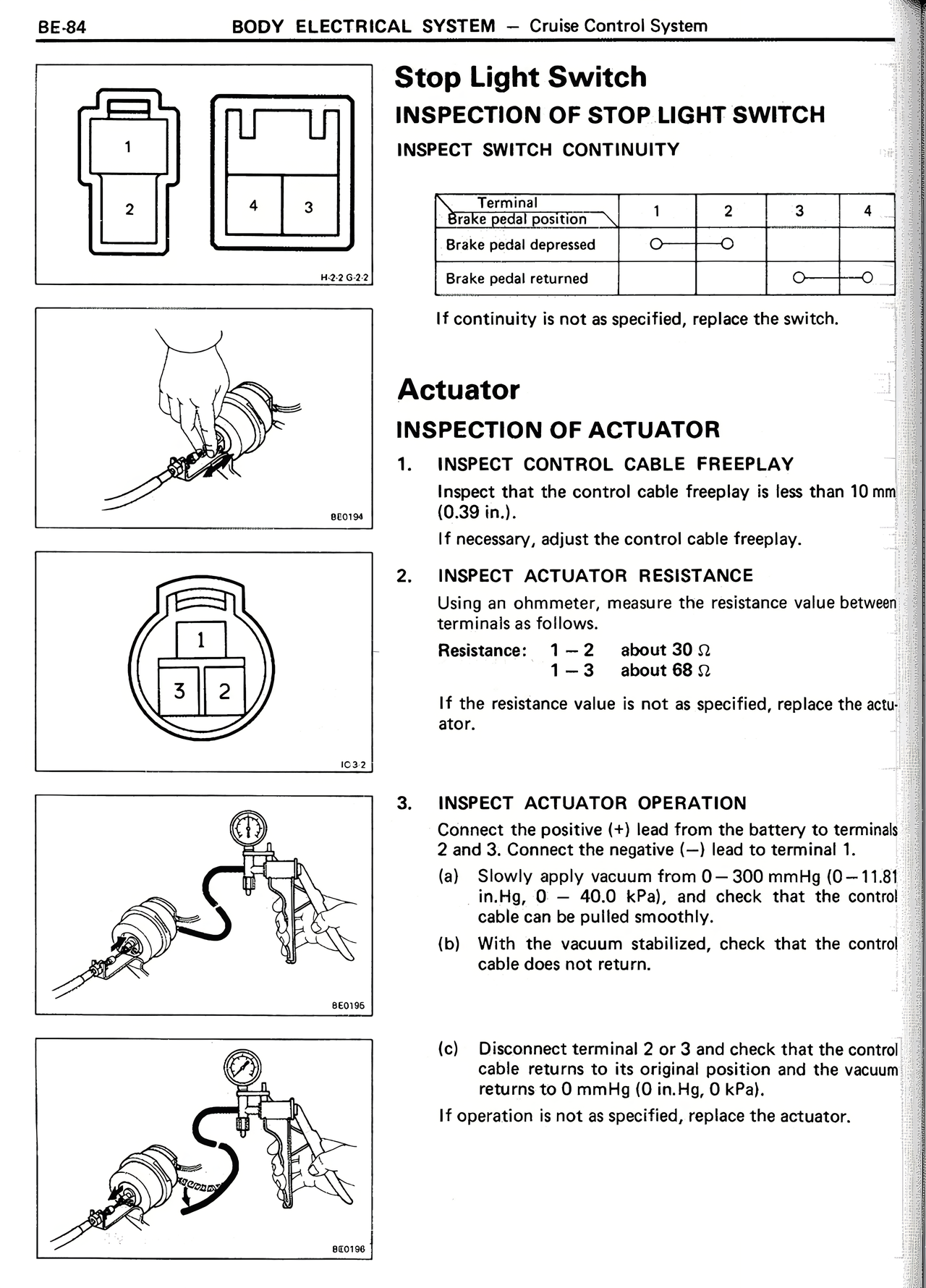
INSPECT SWITCH CONTINUITY
[Diagram showing connector with pins 1, 2 and 4, 3]
Terminal 1 2 3 4
Brake pedal position
Brake pedal depressed O----O
Brake pedal returned O----O
If continuity is not as specified, replace the switch.
Actuator
INSPECTION OF ACTUATOR
1. INSPECT CONTROL CABLE FREEPLAY
Inspect that the control cable freeplay is less than 10 mm (0.39 in.).
If necessary, adjust the control cable freeplay.
2. INSPECT ACTUATOR RESISTANCE
Using an ohmmeter, measure the resistance value between terminals as follows.
Resistance: 1-2 about 30 Ω
1-3 about 68 Ω
If the resistance value is not as specified, replace the actuator.
3. INSPECT ACTUATOR OPERATION
Connect the positive (+) lead from the battery to terminals 2 and 3. Connect the negative (-) lead to terminal 1.
(a) Slowly apply vacuum from 0-300 mmHg (0-11.81 in.Hg, 0 - 40.0 kPa), and check that the control cable can be pulled smoothly.
(b) With the vacuum stabilized, check that the control cable does not return.
(c) Disconnect terminal 2 or 3 and check that the control cable returns to its original position and the vacuum returns to 0 mmHg (0 in.Hg, 0 kPa).
If operation is not as specified, replace the actuator.