100%
REMOTE CONTROL MIRROR
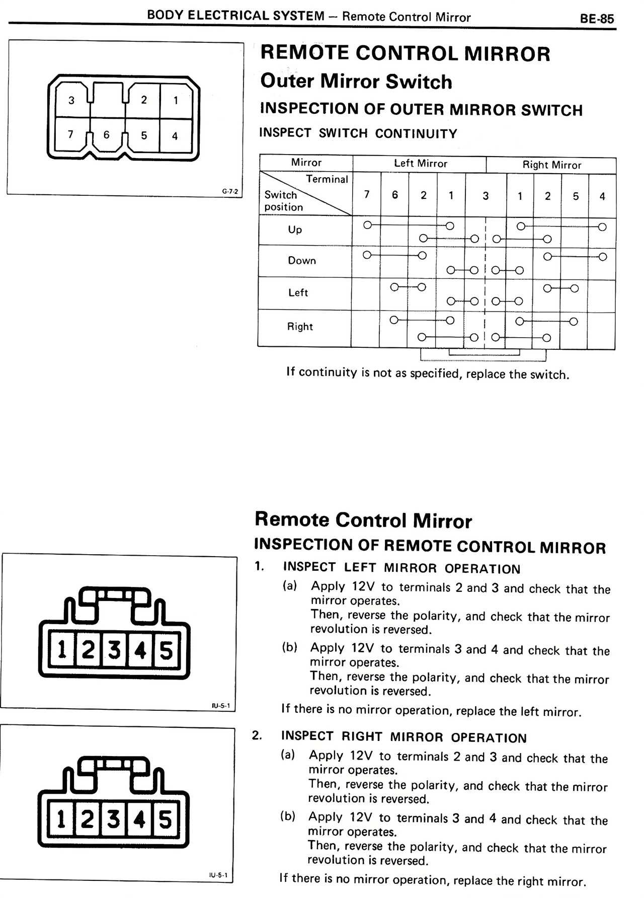
Outer Mirror Switch
INSPECTION OF OUTER MIRROR SWITCH
INSPECT SWITCH CONTINUITY
[DIAGRAM: 7-pin connector layout showing pins numbered 3,2,1 on top row and 7,6,5,4 on bottom row]
Mirror Left Mirror Right Mirror
Terminal 7 8 2 1 3 1 2 5 4
Switch
position
Up O O----O O----O O----O
Down O----O O----O O----O O----O
Left O----O O----O O----O
O----O
Right O----O O----O O----O
O----O O----O
If continuity is not as specified, replace the switch.
Remote Control Mirror
INSPECTION OF REMOTE CONTROL MIRROR
1. INSPECT LEFT MIRROR OPERATION
(a) Apply 12V to terminals 2 and 3 and check that the
mirror operates.
Then, reverse the polarity, and check that the mirror
revolution is reversed.
(b) Apply 12V to terminals 3 and 4 and check that the
mirror operates.
Then, reverse the polarity, and check that the mirror
revolution is reversed.
If there is no mirror operation, replace the left mirror.
2. INSPECT RIGHT MIRROR OPERATION
(a) Apply 12V to terminals 2 and 3 and check that the
mirror operates.
Then, reverse the polarity, and check that the mirror
revolution is reversed.
(b) Apply 12V to terminals 3 and 4 and check that the
mirror operates.
Then, reverse the polarity, and check that the mirror
revolution is reversed.
If there is no mirror operation, replace the right mirror.
[DIAGRAMS: Two identical 5-pin connector layouts showing pins numbered 1,2,3,4,5]