Page text (OCR transcript)
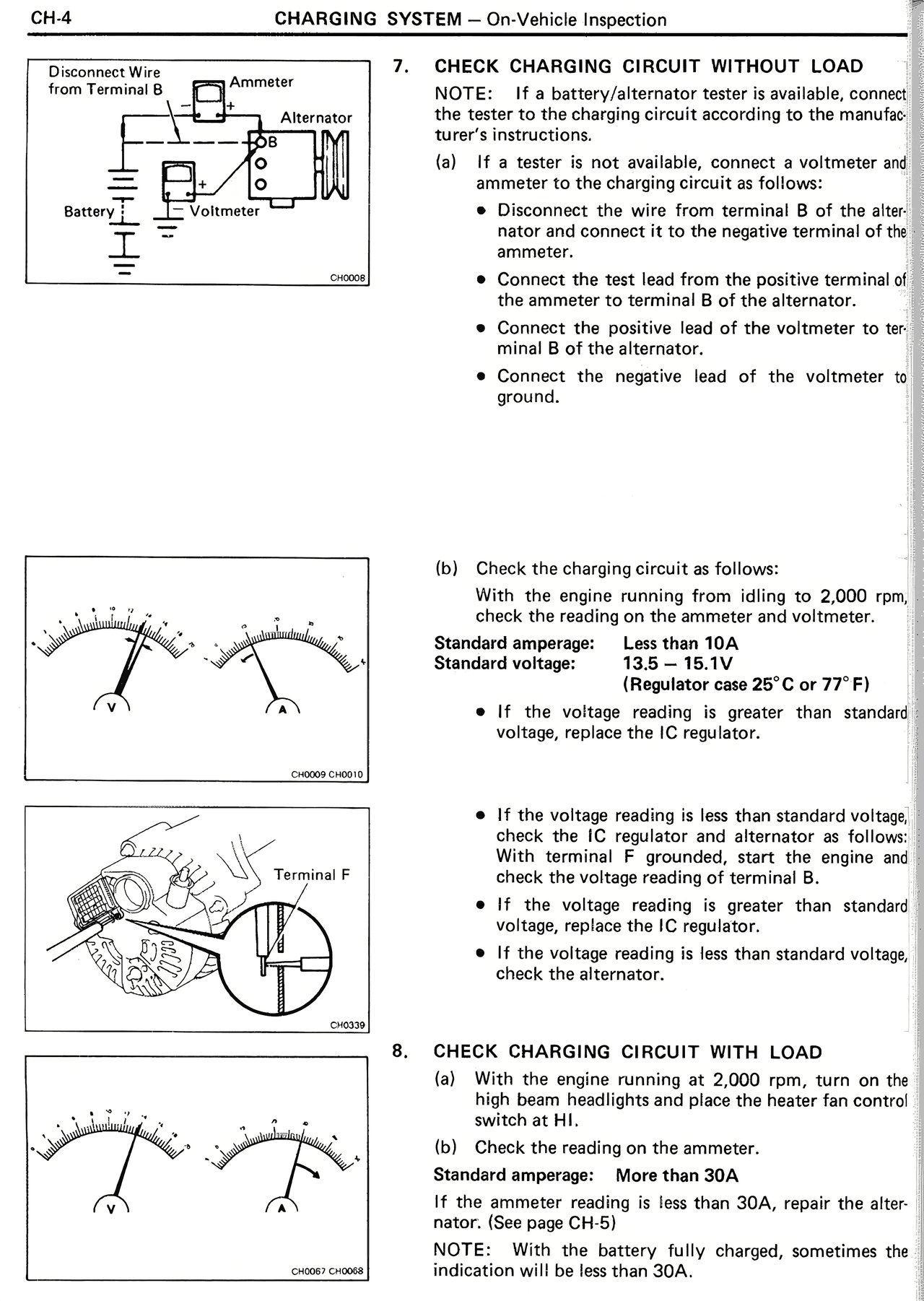
Disconnect Wire
from Terminal B

Ammeter
Alternator

Battery

Voltmeter

CH0405

7. CHECK CHARGING CIRCUIT WITHOUT LOAD

NOTE: If a battery/alternator tester is available, connect the tester to the charging circuit according to the manufacturer's instructions.

(a) If a tester is not available, connect a voltmeter and ammeter to the charging circuit as follows:

• Disconnect the wire from terminal B of the alternator and connect it to the negative terminal of the ammeter.

• Connect the test lead from the positive terminal of the ammeter to terminal B of the alternator.

• Connect the positive lead of the voltmeter to terminal B of the alternator.

• Connect the negative lead of the voltmeter to ground.

(b) Check the charging circuit as follows:

With the engine running from idling to 2,000 rpm, check the reading on the ammeter and voltmeter.

Standard amperage: 10A or less
Standard voltage: 13.5 — 15.1V
(Regulator case 25°C or 77°F)

• If the voltage reading is greater than standard voltage, replace the IC regulator.

• If the voltage reading is less than standard voltage, check the IC regulator and alternator as follows: With terminal F grounded, start the engine and check the voltage reading (terminal B).

• If the voltage reading is greater than standard voltage, replace the IC regulator.

• If the voltage reading is less than standard voltage, check the alternator.

8. CHECK CHARGING CIRCUIT WITH LOAD

(a) With the engine running at 2,000 rpm, turn on the high beam headlights and place the heater fan control switch at HI.

(b) Check the reading on the ammeter.

Standard amperage: More than 30A

If the ammeter reading is less than 30A, repair the alternator. (See page CH-5)

NOTE: With the battery fully charged, sometimes the indication will be less than 30A.

CH0406 / CH0407

Terminal F

CH0619

CH0604 / CH0408