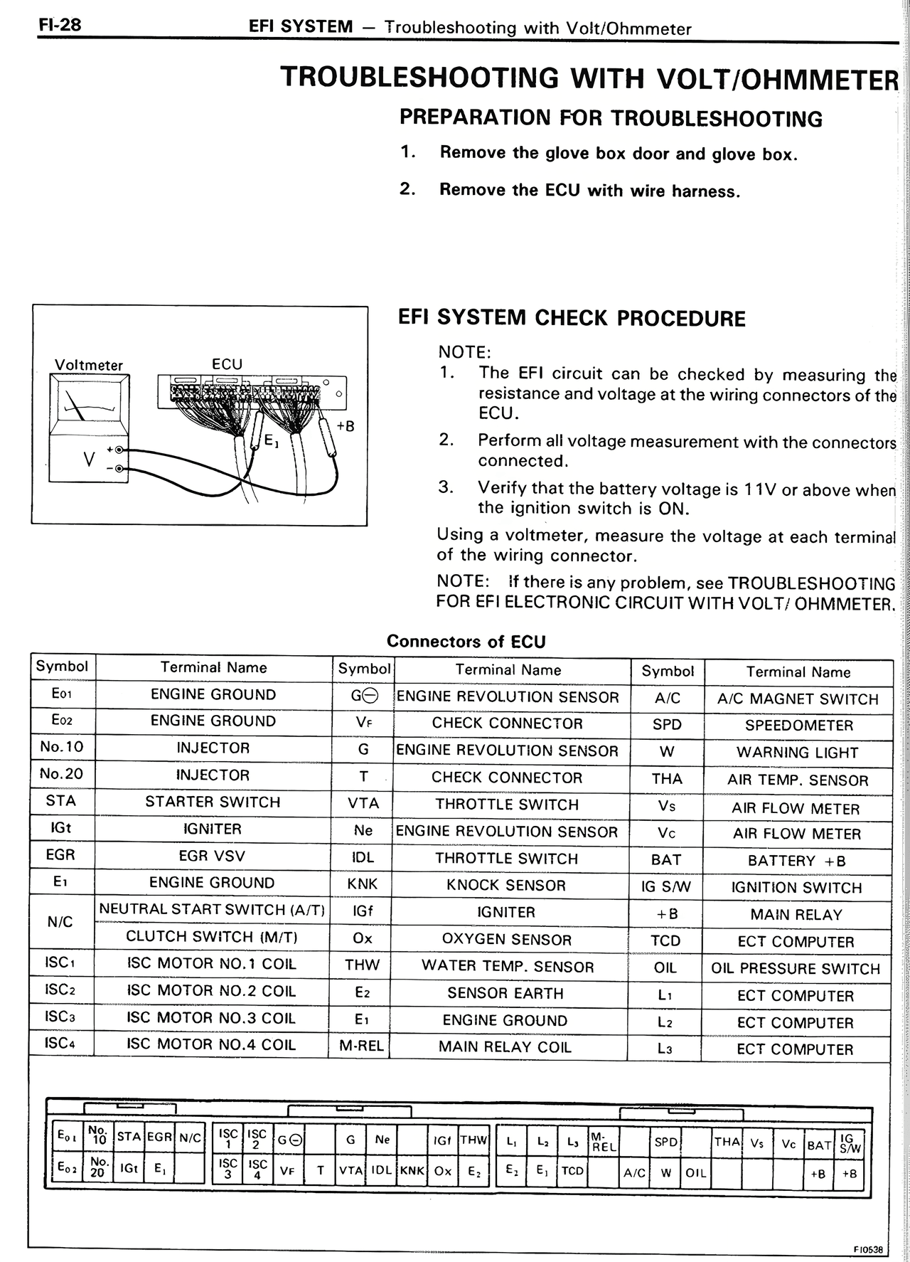
Page text (OCR transcript)
TROUBLESHOOTING WITH VOLT/OHMMETER

PREPARATION FOR TROUBLESHOOTING

1. Remove the glove box door and glove box.

2. Remove the ECU with wire harness.

EFI SYSTEM CHECK PROCEDURE

NOTE:
1. The EFI circuit can be checked by measuring the resistance and voltage at the wiring connectors of the ECU.

2. Perform all voltage measurement with the connectors connected.

3. Verify that the battery voltage is 11V or above when the ignition switch is ON.

Using a voltmeter, measure the voltage at each terminal of the wiring connector.

NOTE: If there is any problem, see TROUBLESHOOTING FOR EFI ELECTRONIC CIRCUIT WITH VOLT/ OHMMETER.

Connectors of ECU

Symbol | Terminal Name | Symbol | Terminal Name | Symbol | Terminal Name
E01 | ENGINE GROUND | G/O | ENGINE REVOLUTION SENSOR | A/C | A/C MAGNET SWITCH
E02 | ENGINE GROUND | V+ | CHECK CONNECTOR | SPD | SPEEDMETER
No.10 | INJECTOR | S | ENGINE REVOLUTION SENSOR | W | WARNING LIGHT
No.20 | INJECTOR | T | CHECK CONNECTOR | THA | AIR TEMP. SENSOR
STA | STARTER SWITCH | VTA | THROTTLE SWITCH | Vc | AIR FLOW METER
IG11 | IGNITER | M | ENGINE REVOLUTION SENSOR | Vs | AIR FLOW METER
EGR | EGR VSV | IDL | THROTTLE SWITCH | BAT | BATTERY - B
E1 | ENGINE GROUND | KNK | KNOCK SENSOR | IG S/W | IGNITION SWITCH
N/C | NEUTRAL START SWITCH (A/T) | IGf | IGNITER | +B | MAIN RELAY
 | CLUTCH SWITCH (M/T) | Ox | OXYGEN SENSOR | TCD | ECT COMPUTER
ISC1 | ISC MOTOR NO.1 COIL | THW | WATER TEMP. SENSOR | OIL | OIL PRESSURE SWITCH
ISC2 | ISC MOTOR NO.2 COIL | E2 | SENSOR EARTH | L1 | ECT COMPUTER
ISC3 | ISC MOTOR NO.3 COIL | E3 | ENGINE GROUND | L2 | ECT COMPUTER
ISC4 | ISC MOTOR NO.4 COIL | M-REL | MAIN RELAY COIL | L3 | ECT COMPUTER

F10638