100%
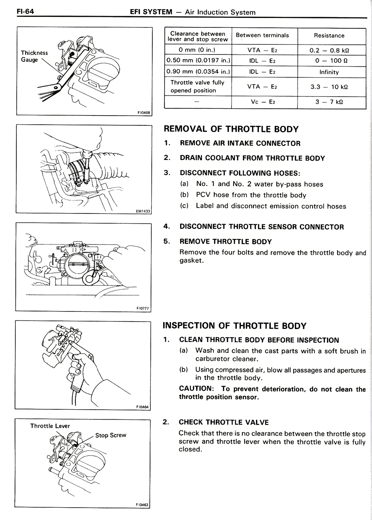
Thickness
Gauge
Clearance between
lever and stop screw
Between terminals
Resistance
—
VTA — E2
0.2 — 0.8 kΩ
0.50 mm (0.0197 in.)
IDL — E2
0 — 100 Ω
0.90 mm (0.0354 in.)
IDL — E2
Infinity
Throttle valve fully
opened position
VTA — E2
3.3 — 10 kΩ
—
Vc — E2
3 — 7 kΩ
REMOVAL OF THROTTLE BODY
1. REMOVE AIR INTAKE CONNECTOR
2. DRAIN COOLANT FROM THROTTLE BODY
3. DISCONNECT FOLLOWING HOSES:
(a) No. 1 and No. 2 water by-pass hoses
(b) PCV hose from the throttle body
(c) Label and disconnect emission control hoses
4. DISCONNECT THROTTLE SENSOR CONNECTOR
5. REMOVE THROTTLE BODY
Remove the four bolts and remove the throttle body and
gasket.
INSPECTION OF THROTTLE BODY
1. CLEAN THROTTLE BODY BEFORE INSPECTION
(a) Wash and clean the cast parts with a soft brush in
carburetor cleaner.
(b) Using compressed air, blow all passages and apertures
in the throttle body.
CAUTION: To prevent deterioration, do not clean the
throttle position sensor.
2. CHECK THROTTLE VALVE
Check that there is no clearance between the throttle stop
screw and throttle lever when the throttle valve is fully
closed.
Throttle Lever
Stop Screw