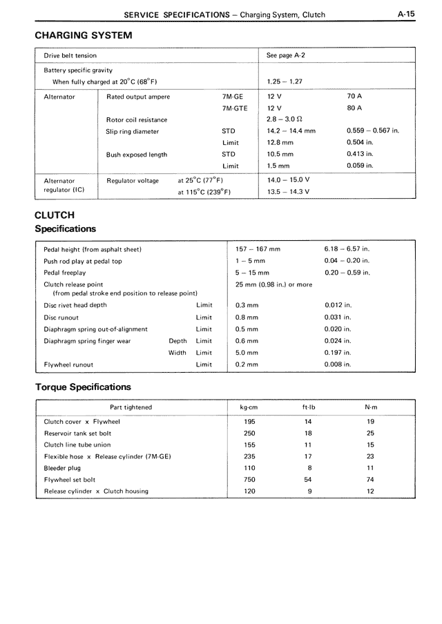
CHARGING SYSTEM
Drive belt tension
See page A-2
Battery specific gravity
When fully charged at 20°C (68°F)
1.25 – 1.27
Alternator
Rated output ampere
7M-GE
12 V
70 A
7M-GTE
12 V
80 A
Rotor coil resistance
2.8 – 3.0 Ω
Slip ring diameter
STD
14.2 – 14.4 mm
0.559 – 0.567 in.
Limit
12.8 mm
0.504 in.
Bush exposed length
STD
10.5 mm
0.413 in.
Limit
1.5 mm
0.059 in.
Alternator regulator (IC)
Regulator voltage
at 25°C (77°F)
14.0 – 15.0 V
at 116°C (230°F)
13.5 – 14.3 V
CLUTCH
Specifications
Pedal height (from asphalt sheet)
157 – 167 mm
6.18 – 6.57 in.
Push rod play at pedal top
1 – 5 mm
0.04 – 0.20 in.
Pedal freeplay
5 – 15 mm
0.20 – 0.59 in.
Clutch release point
25 mm (0.98 in.) or more
(from pedal stroke end position to release point)
Disc rivet head depth
Limit
0.3 mm
0.012 in.
Disc runout
Limit
0.8 mm
0.031 in.
Diaphragm spring out-of-alignment
Limit
0.5 mm
0.020 in.
Diaphragm spring finger wear
Depth
Limit
0.6 mm
0.024 in.
Width
Limit
5.0 mm
0.197 in.
Flywheel runout
Limit
0.2 mm
0.008 in.
Torque Specifications
Part tightened
kg·cm
ft·lb
N·m
Clutch cover × Flywheel
195
14
19
Reservoir tank set bolt
250
18
25
Clutch line tube union
155
11
15
Flexible hose × Release cylinder (7M-GE)
235
17
23
Bleeder plug
110
8
11
Flywheel set bolt
750
54
74
Release cylinder × Clutch housing
120
9
12