SERVICE SPECIFICATIONS — EFI System A-9
Specifications (Cont'd)
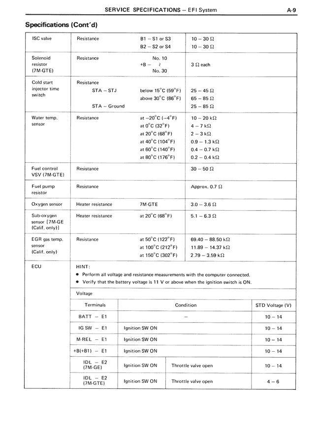
ISC valve Resistance B1 — S1 or S3 10 — 30 Ω
B2 — S2 or S4 10 — 30 Ω
Solenoid Resistance No. 10
resistor +B — , 3 Ω each
(7M-GTE) No. 30
Cold start Resistance
injector time STA — STJ
switch below 15°C (59°F) 25 — 45 Ω
above 30°C (86°F) 65 — 85 Ω
STA — Ground 25 — 85 Ω
Water temp. Resistance at -20°C (-4°F) 10 — 20 kΩ
sensor at 0°C (32°F) 4 — 7 kΩ
at 20°C (68°F) 2 — 3 kΩ
at 40°C (104°F) 0.9 — 1.3 kΩ
at 60°C (140°F) 0.4 — 0.7 kΩ
at 80°C (176°F) 0.2 — 0.4 kΩ
Fuel control Resistance 30 — 50 Ω
VSV (7M-GTE)
Fuel pump Resistance Approx. 0.7 Ω
resistor
Oxygen sensor Heater resistance 7M-GTE 3.0 — 3.6 Ω
Sub-oxygen Heater resistance at 20°C (68°F) 5.1 — 6.3 Ω
sensor (7M-GE
(Calif. only))
EGR gas temp. Resistance at 50°C (122°F) 69.40 — 88.50 kΩ
sensor at 100°C (212°F) 11.89 — 14.37 kΩ
(Calif. only) at 150°C (302°F) 2.79 — 3.59 kΩ
ECU HINT:
• Perform all voltage and resistance measurements with the computer connected.
• Verify that the battery voltage is 11 V or above when the ignition switch is ON.
Voltage
Terminals Condition STD Voltage (V)
BATT — E1 10 — 14
IG SW — E1 Ignition SW ON 10 — 14
M-REL — E1 Ignition SW ON 10 — 14
+B(+B1) — E1 Ignition SW ON 10 — 14
IDL — E2 Ignition SW ON Throttle valve open 10 — 14
(7M-GE)
IDL — E2 Ignition SW ON Throttle valve open 4 — 6
(7M-GTE)