NOTICE: When connecting the battery after clearing the malfunction code, always do it with the ignition switch in LOCK position. When the battery has been reconnected, turn the ignition switch to ACC or ON position after at least 2 seconds have elapsed.
If the battery is reconnected with the ignition switch in ACC or ON position, or the ignition switch is turned to ACC or ON within 2 seconds of connecting the battery, it is possible that the diagnosis system will not operate normally.
HINT: Determine the malfunction in the airbag system in step 6 by whether or not a malfunction code other than code 41 is output.
7 DIAGNOSTIC CODE CHART
Proceed to the appropriate flow chart in step 8 in accordance with the malfunction code found in step 5 or 6.
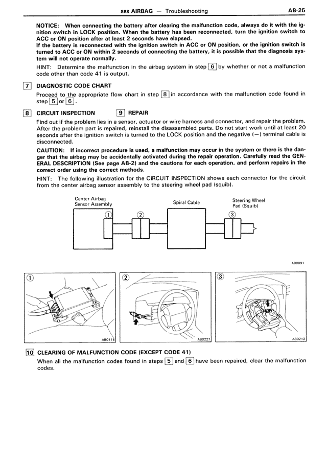
8 CIRCUIT INSPECTION 9 REPAIR
Find out if the problem lies in a sensor, actuator or wire harness and connector, and repair the problem. After the problem part is repaired, reinstall the disassembled parts. Do not start work until at least 20 seconds after the ignition switch is turned to the LOCK position and the negative (—) terminal cable is disconnected.
CAUTION: If incorrect procedure is used, a malfunction may occur in the system or there is the danger that the airbag may be accidentally activated during the repair operation. Carefully read the GEN-ERAL DESCRIPTION (See page AB-2) and the cautions for each operation, and perform repairs in the correct order during the repair work.
HINT: The following illustration for the CIRCUIT INSPECTION shows each connector for the circuit from the center airbag sensor assembly to the steering wheel pad (squib).
Center Airbag Spiral Cable Steering Wheel
Sensor Assembly Pad (Squib)
① ② ③
[diagram showing connectors]
[Three diagrams labeled AB0091, AB0222, AB0213 showing locations of components 1, 2, and 3]
10 CLEARING OF MALFUNCTION CODE (EXCEPT CODE 41)
When all the malfunction codes found in steps 5 and 6 have been repaired, clear the malfunction codes.