Interior Room Temperature Control System & Blower Speed Control System (Cont'd)
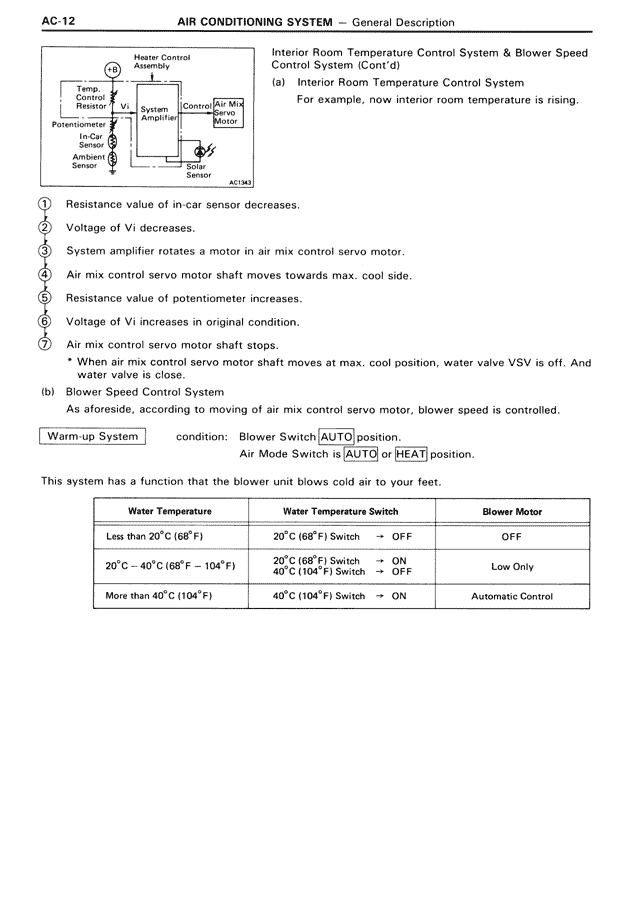
(a) Interior Room Temperature Control System
For example, now interior room temperature is rising.
[DIAGRAM showing Heater Control Assembly with components: Temp. Control Dial, Potentiometer, In-Car Sensor, Ambient Sensor, Vi, Vt, System Amplifier, Control Air Mix Servo Motor, Air Mix Control Servo Motor]
① Resistance value of in-car sensor decreases.
② Voltage of Vi decreases.
③ System amplifier rotates a motor in air mix control servo motor.
④ Air mix control servo motor shaft moves towards max. cool side.
⑤ Resistance value of potentiometer increases.
⑥ Voltage of Vt increases in original condition.
⑦ Air mix control servo motor shaft stops.
* When air mix control servo motor shaft moves at max. cool position, water valve VSV is off. And water valve is close.
(b) Blower Speed Control System
As aforesaid, according to moving of air mix control servo motor, blower speed is controlled.
Warm-up System condition: Blower Switch AUTO position.
Air Mode Switch is AUTO or HEAT position.
This system has a function that the blower unit blows cold air to your feet.
[TABLE:
Water Temperature | Water Temperature Switch | Blower Motor
Less than 20°C (68°F) | 20°C (68°F) Switch → OFF | OFF
20°C ~ 40°C (68°F ~ 104°F) | 20°C (68°F) Switch → ON, 40°C (104°F) Switch → OFF | Low Only
More than 40°C (104°F) | 40°C (104°F) Switch → ON | Automatic Control]