AT-30 AUTOMATIC TRANSMISSION — Troubleshooting (Electronic Control System)
Terminal | Measuring condition | Voltage (V)
S₁ - GND | - | 12
S₁, S₂ - GND | - | 0
OD₁ - GND | Coolant temp. below 60°C (140°F) | 0
| Coolant temp. above 60°C (140°F) | 12
OD₂ - GND | O/D main switch turned ON | 12
| O/D main switch turned OFF | 0
IG - GND | Ignition switch ON | 12
SP₁ - GND | Standing still | 5 or 0
| Vehicle moving | 12
PWR - GND | PWR pattern | 12
| NORM pattern | 0 ~ 2
+B - GND | - | 12
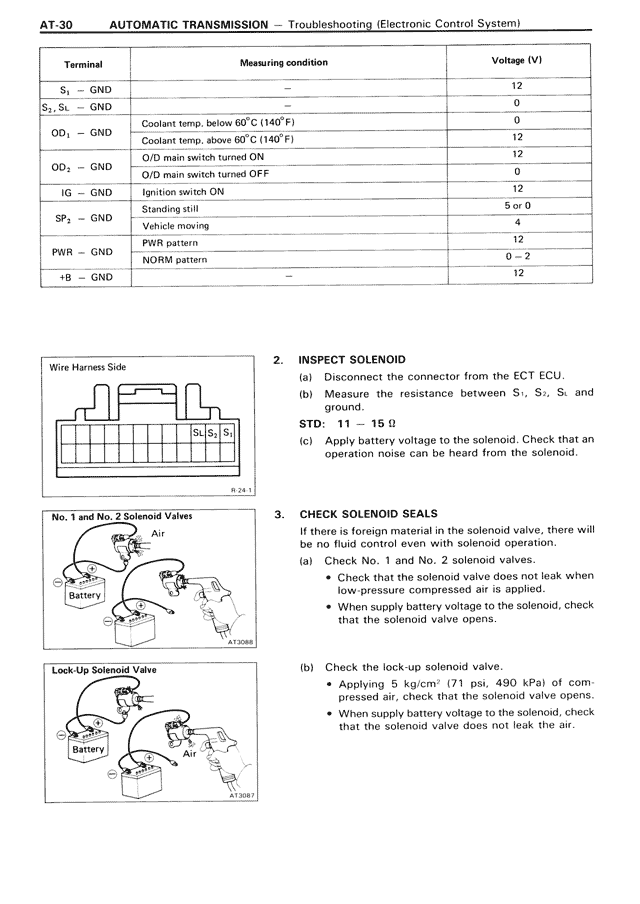
Wire Harness Side
[Diagram showing wire harness connector with S₁S₂S₁ labeled]
B-26.1
No. 1 and No. 2 Solenoid Valves
[Diagram showing No. 1 and No. 2 solenoid valves with air flow and battery connection]
B-27.008
Lock Up Solenoid Valve
[Diagram showing lock-up solenoid valve with air flow and battery connection]
B-28B.7
2. INSPECT SOLENOID
(a) Disconnect the connector from the ECT ECU.
(b) Measure the resistance between S₁, S₂, S₃ and ground.
STD: 11 ~ 15 Ω
(c) Apply battery voltage to the solenoid. Check that an operation noise can be heard from the solenoid.
3. CHECK SOLENOID SEALS
If there is foreign material in the solenoid valve, there will be no fluid control even with solenoid operation.
(a) Check No. 1 and No. 2 solenoid valves.
• Check that the solenoid valve does not leak when low-pressure compressed air is applied.
• When supply battery voltage to the solenoid, check that the solenoid valve opens.
(b) Check the lock-up solenoid valve.
• Applying 5 kg/cm² (71 psi, 490 kPa) of compressed air, check that the solenoid valve opens.
• When supply battery voltage to the solenoid, check that the solenoid valve does not leak the air.