If a malfunction is found during voltage inspection (step 1.), inspect the components listed below.
4. INSPECT NEUTRAL START SWITCH
(See page AT-41)
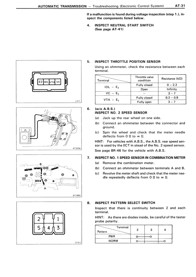
5. INSPECT THROTTLE POSITION SENSOR
Using an ohmmeter, check the resistance between each terminal.
Terminal | Throttle valve condition | Resistance (kΩ)
IDL — E₂ | Fully closed | 0 - 2.3
IDL — E₂ | Open | Infinity
VC — E₂ | - | 3 - 7
VTA — E₂ | Fully closed | 0.2 - 0.8
VTA — E₂ | Fully open | 3 - 7
6. (w/o A.B.S.)
INSPECT NO. 2 SPEED SENSOR
(a) Jack up the rear wheel on one side.
(b) Connect an ohmmeter between the connector and ground.
(c) Spin the wheel and check that the meter needle deflects from 0 Ω to ∞ Ω.
HINT: For vehicles with A.B.S., the A.B.S. rear speed sensor is used by the ECT instead of the No. 2 speed sensor.
See page BR-46 for the vehicle with A.B.S.
7. INSPECT NO. 1 SPEED SENSOR IN COMBINATION METER
(a) Remove the combination meter.
(b) Connect an ohmmeter between terminals A and B.
(c) Revolve the meter shaft and check that the meter needle repeatedly deflects from 0 Ω to ∞ Ω.
8. INSPECT PATTERN SELECT SWITCH
Inspect that there is continuity between 2 and each terminal.
HINT: As there are diodes inside, be careful of the tester probe polarity.
Pattern | Terminal
| 2 | 3 | 4
PWR | O-|—O |
NORM | O | |-O