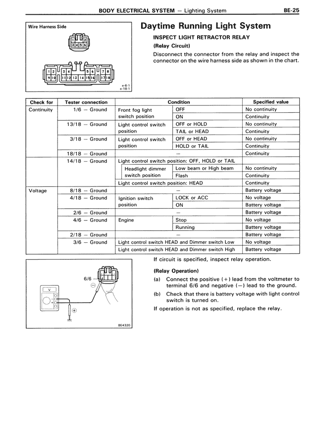
Wire Harness Side
Daytime Running Light System
INSPECT LIGHT RETRACTOR RELAY
(Relay Circuit)
Disconnect the connector from the relay and inspect the connector on the wire harness side as shown in the chart.
Check for | Tester connection | Condition | Specified value
Continuity | 1/6 — Ground | Front fog light switch position | OFF | No continuity
| | | ON | Continuity
| 13/18 — Ground | Light control switch position | OFF or HOLD | No continuity
| | | TAIL or HEAD | Continuity
| 3/18 — Ground | Light control switch position | OFF or HEAD | No continuity
| | | HOLD or TAIL | Continuity
| 18/18 — Ground | | | Continuity
| 14/18 — Ground | Light control switch position: OFF, HOLD or TAIL | |
| | Headlight dimmer switch position | Low beam or High beam | No continuity
| | | Flash | Continuity
| | Light control switch position: HEAD | | Continuity
Voltage | 8/18 — Ground | | | Battery voltage
| 4/18 — Ground | Ignition switch position | LOCK or ACC | No voltage
| | | ON | Battery voltage
| 2/6 — Ground | | | Battery voltage
| 4/6 — Ground | Engine | Stop | No voltage
| | | Running | Battery voltage
| 2/18 — Ground | | | Battery voltage
| 3/6 — Ground | Light control switch HEAD and Dimmer switch Low | | No voltage
| | Light control switch HEAD and Dimmer switch High | | Battery voltage
If circuit is specified, inspect relay operation.
(Relay Operation)
(a) Connect the positive (+) lead from the voltmeter to terminal 6/6 and negative (—) lead to the ground.
(b) Check that there is battery voltage with light control switch is turned on.
If operation is not as specified, replace the relay.