BE-24 BODY ELECTRICAL SYSTEM — Lighting System
Voltage
17 — Ground (U.S.A. only) | Light switch HEAD, Dimmer switch Low and Front Fog switch ON | Battery voltage
| Any other position | No voltage
3 — Ground | Light control switch position | OFF or HEAD | No continuity
| | HOLD or TAIL | Continuity
13 — Ground | Light control switch position | OFF or HOLD | No continuity
6, 16 — Ground | | TAIL or HEAD | Continuity
| | | Continuity
Continuity | Light control switch position: OFF, HOLD or TAIL |
14 — Ground | Headlight dimmer switch position | Low beam or High beam Flash | No continuity
| | | Continuity
5 — 1 | Light control switch position: HEAD | Continuity
| Headlight lowermost position | No continuity
7 — 1 | Headlight any position except lowermost position | Continuity
5 — 9 | Headlight uppermost position | No continuity
7 — 9 | Headlight any position except uppermost position | Continuity
11 — Ground (U.S.A. only) | Theft deterrent system does not operate | No continuity
| Theft deterrent system is operating | Alternates continuity/no continuity
[THIS IS FIGURE: Diagram showing a relay component with numbered terminals 1-5 and connection points]
If circuit is as specified, replace the relay.
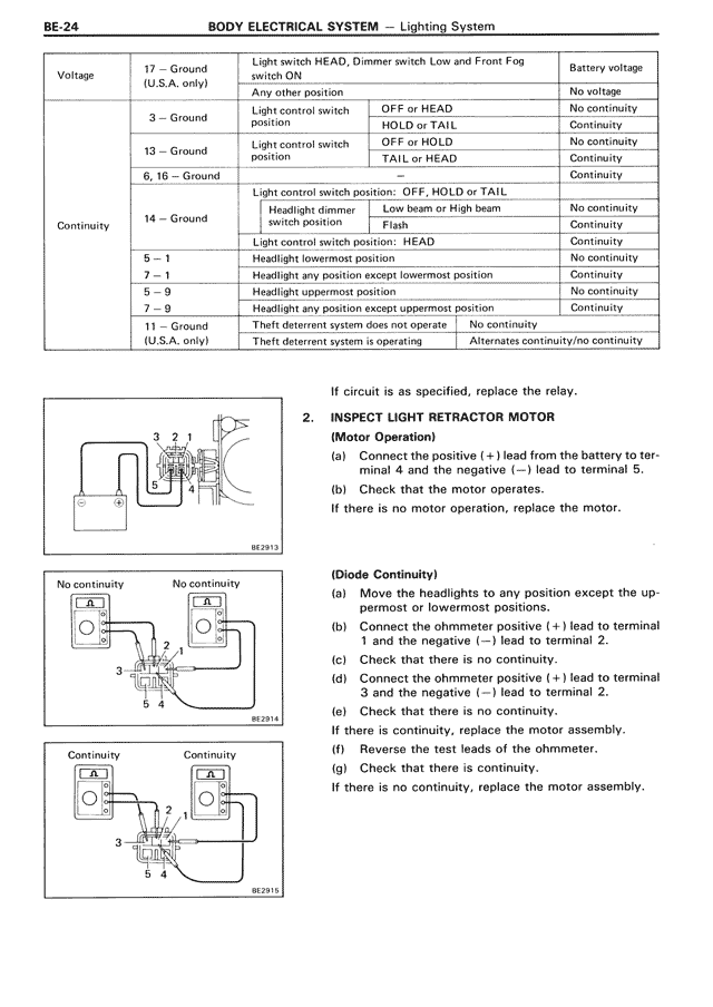
2. INSPECT LIGHT RETRACTOR MOTOR
(Motor Operation)
(a) Connect the positive (+) lead from the battery to terminal 4 and the negative (—) lead to terminal 5.
(b) Check that the motor operates.
If there is no motor operation, replace the motor.
[THIS IS FIGURE: Four diagrams showing different continuity test configurations for terminals 1-5, labeled as "No continuity" and "Continuity" with diagrams BE2913, BE2914, and BE2915]
(Diode Continuity)
(a) Move the headlights to any position except the uppermost or lowermost positions.
(b) Connect the ohmmeter positive (+) lead to terminal 1 and the negative (—) lead to terminal 2.
(c) Check that there is no continuity.
(d) Connect the ohmmeter positive (+) lead to terminal 3 and the negative (—) lead to terminal 2.
(e) Check that there is no continuity.
If there is continuity, replace the motor assembly.
(f) Reverse the test leads of the ohmmeter.
(g) Check that there is continuity.
If there is no continuity, replace the motor assembly.