2. MEASURE RECEIVER GAUGE RESISTANCE
Measure the resistance between terminals.
Resistance: Approx. 42 Ω
If resistance value is not as specified, replace the receiver gauge.
3. INSPECT SENDER GAUGE OPERATION
(a) Disconnect the connector from the sender gauge.
(b) Apply battery voltage to sender gauge terminal through a 3.4 W test bulb.
(c) Check that the bulb does not light when the engine is stopped.
(d) Check that the bulb flashes when the engine is running.
The number of flashes should vary with engine speed.
If operations are not as specified, replace the sender gauge.
Brake Warning
INSPECTION OF BRAKE WARNING
1. INSPECT WARNING LIGHT OPERATION
(a) Disconnect the connectors from the level warning switch and parking brake switch.
(b) Connect the terminals on the wire harness side of the level warning switch connector.
(c) Disconnect the connector from the alternator and turn the ignition switch ON.
(d) Check that the warning light lights.
If the warning light does not light, test the bulb.
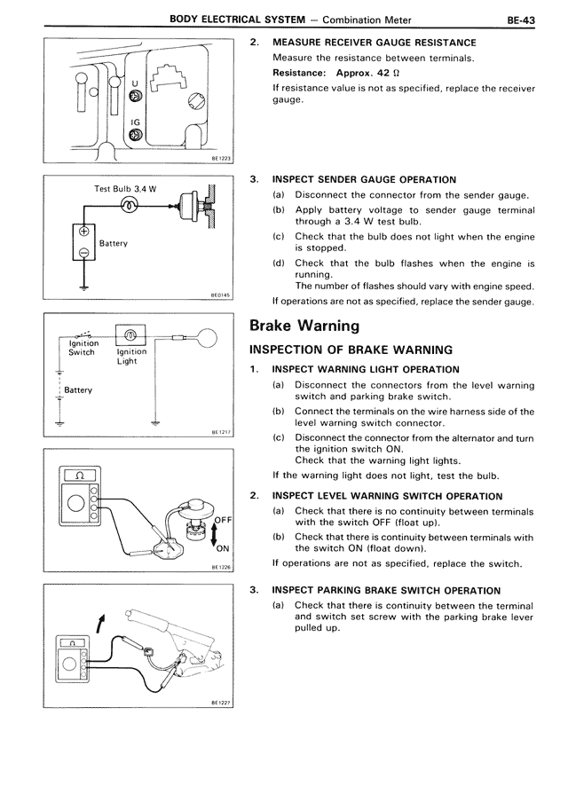
2. INSPECT LEVEL WARNING SWITCH OPERATION
(a) Check that there is no continuity between terminals with the switch OFF (float up).
(b) Check that there is continuity between terminals with the switch ON (float down).
If operations are not as specified, replace the switch.
3. INSPECT PARKING BRAKE SWITCH OPERATION
(a) Check that there is continuity between the terminal and switch set screw with the parking brake lever pulled up.