Turbo Meter
INSPECTION OF METER
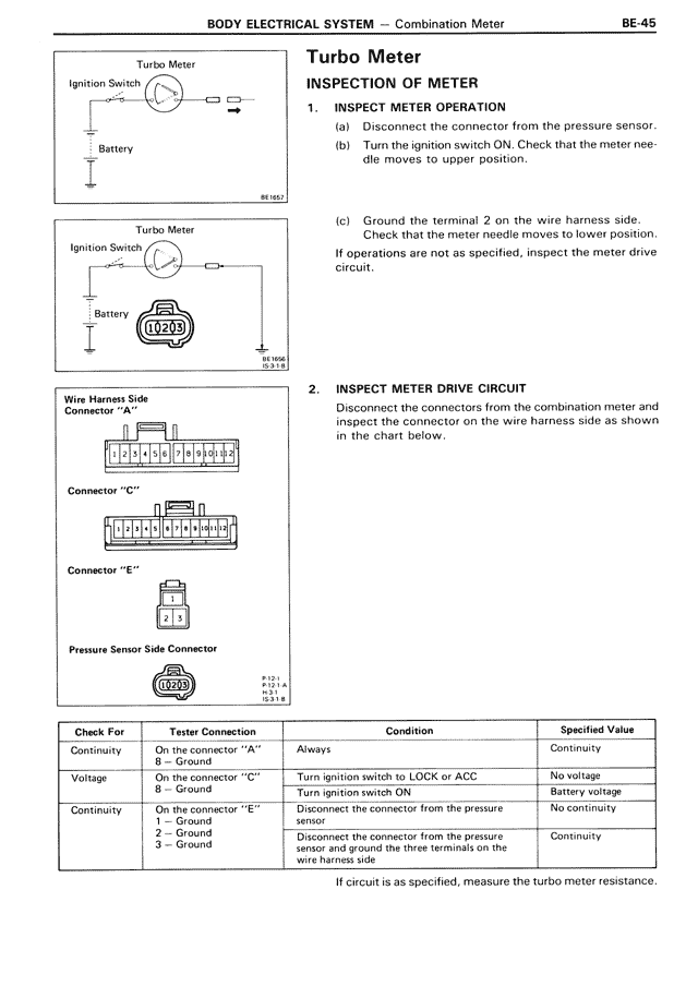
1. INSPECT METER OPERATION
(a) Disconnect the connector from the pressure sensor.
(b) Turn the ignition switch ON. Check that the meter needle moves to upper position.
(c) Ground the terminal 2 on the wire harness side. Check that the meter needle moves to lower position.
If operations are not as specified, inspect the meter drive circuit.
2. INSPECT METER DRIVE CIRCUIT
Disconnect the connectors from the combination meter and inspect the connector on the wire harness side as shown in the chart below.
Check For | Tester Connection | Condition | Specified Value
Continuity | On the connector "A" 1 — Ground | Always | Continuity
Voltage | On the connector "C" B — Ground | Turn ignition switch to LOCK or ACC Turn ignition switch ON | No voltage Battery voltage
Continuity | On the connector "E" 1 — Ground 2 — Ground 3 — Ground | Disconnect the connector from the pressure sensor and ground the three terminals on the wire harness side | No continuity Continuity
If circuit is as specified, measure the turbo meter resistance.