BE-52 BODY ELECTRICAL SYSTEM — Door Lock Control System
Check For Tester Connection Condition Specified Value
Continuity 2 — Body ground LH door opened Continuity
LH door closed No continuity
Voltage 8 — Body ground Battery voltage
10 — Body ground Turn the following switches, one by one to lock
• Control switch • LH door key switch
• RH door key switch Continuity
Turn the following switches, one by one to except lock
• Control switch • LH door key switch
• RH door key switch No continuity
14 — Body ground RH door opened Continuity
RH door closed No continuity
Continuity 6 — Body ground LH door lock switch to unlock Continuity
LH door lock switch to lock No continuity
16 — Body ground Continuity
5 — Body ground RH door lock switch to unlock Continuity
RH door lock switch to lock No continuity
7 — Body ground Set the ignition key switch Continuity
Remove the ignition key switch No continuity
11 — Body ground Turn the following switches, one by one to unlock
• Control switch • LH door key switch
• RH door key switch Continuity
Turn the following switches, one by one to except unlock
• Control switch • LH door key switch
• RH door key switch No continuity
(b) Connect the positive (+) lead from the battery to terminal 4 and the negative (—) lead to terminal 3. Check that the solenoids operate lock direction. Then, reverse the polarity, check that the solenoids operate unlock direction. If any of the solenoids does not operate, remove and test the solenoid.
If circuit operation is correct, replace the relay.
Door Lock Solenoid
INSPECTION OF DOOR LOCK SOLENOID
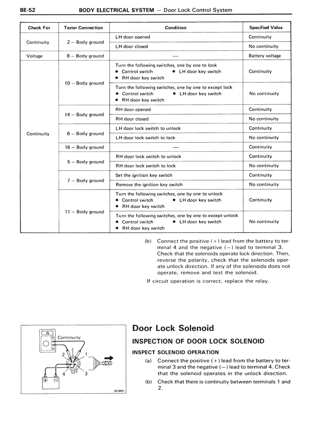
INSPECT SOLENOID OPERATION
(a) Connect the positive (+) lead from the battery to terminal 3 and the negative (—) lead to terminal 4. Check that the solenoid operates in the unlock direction.
(b) Check that there is continuity between terminals 1 and 2.