BODY ELECTRICAL SYSTEM — Door Lock Control System, Remove Control Mirror BE-53
(c) Connect the positive (+) lead from the battery to terminal 4 and the negative (−) lead to terminal 3. Check that the solenoid operates in the lock direction.
(d) Check that there is no continuity between terminals 1 and 2.
If operation is not as specified, replace the solenoid.
REMOTE CONTROL MIRROR
Mirror Switch
INSPECTION OF SWITCH
INSPECT SWITCH CONTINUITY
Inspect the switch continuity between terminals.
Left/Right Changing
switch position LEFT OFF RIGHT
Terminal 1 2 3 7 8 1 2 3 1 2 3 5 6
Control switch position
OFF O————O———O———O O————O O————O———O
UP O———O O————O O————O O————O———O
DOWN O———O O————O O————O O————O———O
LEFT O———O O————O O————O O————O
RIGHT O———O O————O O————O O———O O————O
If continuity is not as specified, replace the switch.
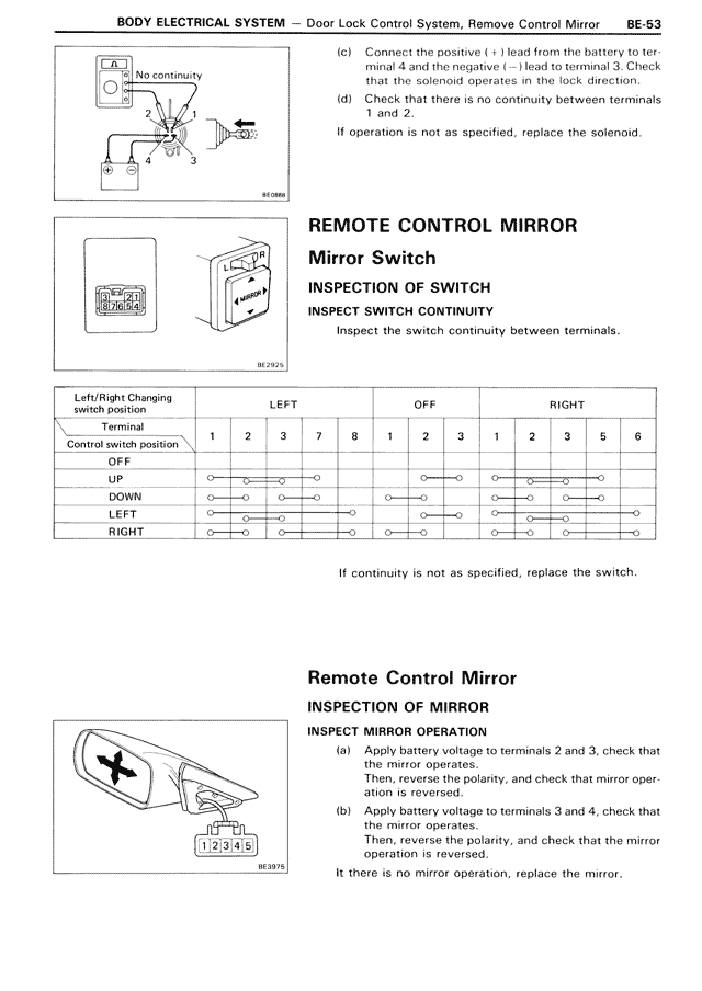
Remote Control Mirror
INSPECTION OF MIRROR
INSPECT MIRROR OPERATION
(a) Apply battery voltage to terminals 2 and 3, check that the mirror operates.
Then, reverse the polarity, and check that mirror operation is reversed.
(b) Apply battery voltage to terminals 3 and 4, check that the mirror operates.
Then, reverse the polarity, and check that the mirror operation is reversed.
It there is no mirror operation, replace the mirror.