BR-52
BRAKE SYSTEM — Anti-lock Brake System (A.B.S.)
[DIAGRAM: Shows actuator check connector with wiring]
BR3164
[DIAGRAM: Shows timing diagram for 1st Digit and 2nd Digit blinks]
1st Digit 2nd Digit
0.5s 2.5s 1.5s 4s
BR3151
[DIAGRAM: Shows normal operation timing - 0.25 seconds ON/OFF pattern]
0.25 seconds
ON
OFF
0.25 seconds
AT018
3. READ DIAGNOSTIC CODE
(a) Turn the ignition switch on.
(b) Disconnect the actuator check connector.
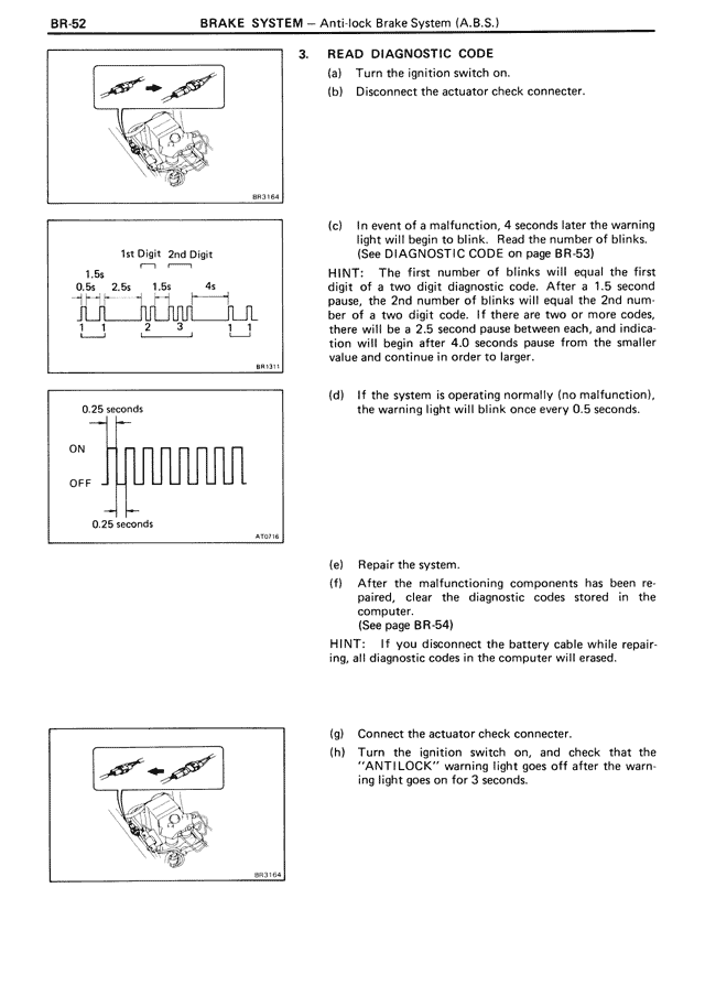
(c) In event of a malfunction, 4 seconds later the warning light will begin to blink. Read the number of blinks.
(See DIAGNOSTIC CODE on page BR-53)
HINT: The first number of blinks will equal the first digit of a two digit diagnostic code. After a 1.5 second pause, the 2nd number of blinks will equal the 2nd number of a two digit code. If there are two or more codes, there will be a 2.5 second pause between each, and indication will begin after 4.0 seconds pause from the smaller value and continue in order to larger.
(d) If the system is operating normally (no malfunction), the warning light will blink once every 0.5 seconds.
(e) Repair the system.
(f) If you wish malfunctioning components has been repaired, clear the diagnostic codes stored in the computer.
(See page BR-54)
HINT: If you disconnect the battery cable while repairing, all diagnostic codes in the computer will be erased.
[DIAGRAM: Shows actuator check connector reconnection]
BR3164
(g) Connect the actuator check connector.
(h) Turn the ignition switch on, and check that the "ANTILOCK" warning light goes off after the warning light goes on for 3 seconds.