CH-4 CHARGING SYSTEM — On-Vehicle Inspection
[DIAGRAM: Illustration showing alternator inspection]
CH0463
5. VISUALLY CHECK ALTERNATOR WIRING AND LISTEN FOR ABNORMAL NOISES
(a) Check that the wiring is in good condition.
(b) Check that there is no abnormal noise from the alternator while the engine is running.
6. INSPECT DISCHARGE WARNING LIGHT CIRCUIT
(a) Warm up the engine and turn it off.
(b) Turn off all accessories.
(c) Turn the ignition switch to ON. Check that the discharge warning light is lit.
(d) Start the engine. Check that the light goes out.
If the light does not operate as specified, troubleshoot the warning light circuit.
[DIAGRAM: Electrical circuit diagram showing Battery, Ammeter, Voltmeter, and Alternator connections with Terminal B labeled]
CH0292
7. CHECK CHARGING CIRCUIT WITHOUT LOAD
HINT: If a battery/alternator tester is available, connect the tester to the charging circuit according to the manufacturer's instructions.
(a) If a tester is not available, connect a voltmeter and ammeter to the charging circuit as follows:
• Disconnect the wire from terminal B of the alternator and connect the wire to the negative (−) terminal of the ammeter.
• Connect the test lead from the positive (+) terminal of the ammeter to terminal B of the alternator.
• Connect the positive (+) lead of the voltmeter to terminal B of the alternator.
• Ground the negative (−) lead of the voltmeter.
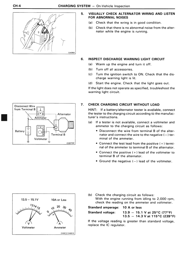
(b) Check the charging circuit as follows:
With the engine running from idling to 2,000 rpm, check the reading on the ammeter and voltmeter.
Standard amperage: 10 A or less
Standard voltage: 13.9 — 15.1 V at 25°C (77°F)
13.5 — 14.3 V at 115°C (239°F)
If the voltage reading is greater than standard voltage, replace the IC regulator.
[DIAGRAM: Two gauge illustrations showing Voltmeter reading 13.5-15.1V and Ammeter reading 10A or Less]
CH0432 CH0015