ENGINE MECHANICAL — Cylinder Block
EM-85
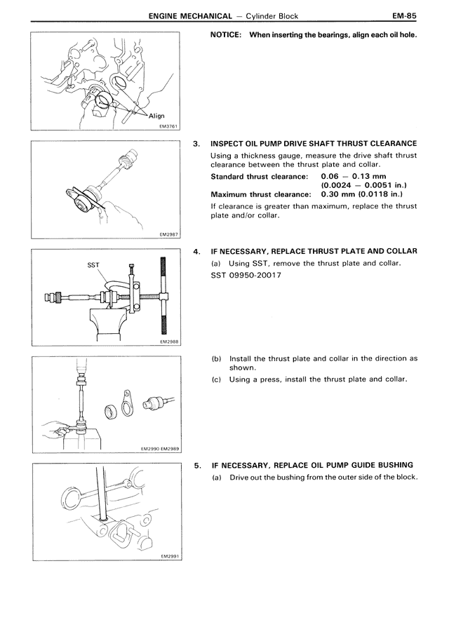
NOTICE: When inserting the bearings, align each oil hole.
[Image EM2363 showing alignment]
[Image EM2887 showing SST]
SST
[Image EM2888 showing installation]
[Image EM2391 showing oil pump guide bushing]
3. INSPECT OIL PUMP DRIVE SHAFT THRUST CLEARANCE
Using a thickness gauge, measure the drive shaft thrust clearance between the thrust plate and collar.
Standard thrust clearance: 0.06 — 0.13 mm
(0.0024 — 0.0051 in.)
Maximum thrust clearance: 0.30 mm (0.0118 in.)
If clearance is greater than maximum, replace the thrust plate and/or collar.
4. IF NECESSARY, REPLACE THRUST PLATE AND COLLAR
(a) Using SST, remove the thrust plate and collar.
SST 09950-20017
(b) Install the thrust plate and collar in the direction as shown.
(c) Using a press, install the thrust plate and collar.
5. IF NECESSARY, REPLACE OIL PUMP GUIDE BUSHING
(a) Drive out the bushing from the outer side of the block.