3. INSPECT BALL JOINT FOR ROTATION CONDITION
(a) Remove the ball joints.
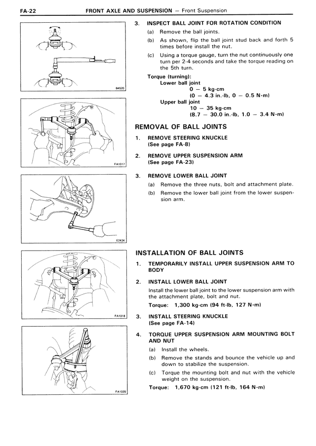
(b) As shown, flip the ball joint stud back and forth 5 times before install the nut.
(c) Using a torque gauge, turn the nut continuously one turn per 2-4 seconds and take the torque reading on the 5th turn.
Torque (turning):
Lower ball joint
5 – 5 kg-cm
(4.3 in.-lb, 0 – 0.5 N-m)
Upper ball joint
10 – 35 kg-cm
(8.7 – 30.0 in.-lb, 1.0 – 3.4 N-m)
REMOVAL OF BALL JOINTS
1. REMOVE STEERING KNUCKLE
(See page FA-8)
2. REMOVE UPPER SUSPENSION ARM
(See page FA-23)
3. REMOVE LOWER BALL JOINT
(a) Remove the three nuts, bolt and attachment plate.
(b) Remove the lower ball joint from the lower suspension arm.
INSTALLATION OF BALL JOINTS
1. TEMPORARILY INSTALL UPPER SUSPENSION ARM TO BODY
2. INSTALL LOWER BALL JOINT
Install the lower ball joint to the lower suspension arm with the attachment plate, bolt and nut.
Torque: 1,300 kg-cm (94 ft-lb, 127 N-m)
3. INSTALL STEERING KNUCKLE
(See page FA-14)
4. TORQUE UPPER SUSPENSION ARM MOUNTING BOLT AND NUT
(a) Install the wheels.
(b) Remove the stands and bounce the vehicle up and down to stabilize the suspension.
(c) Torque the mounting bolt and nut with the vehicle weight on the suspension.
Torque: 1,670 kg-cm (121 ft-lb, 164 N-m)