FI-116
EFI SYSTEM — Electronic Control System
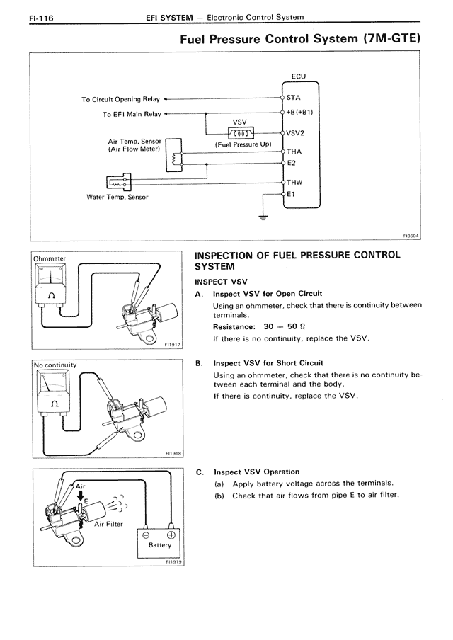
Fuel Pressure Control System (7M-GTE)
[DIAGRAM showing ECU connections with:
To Circuit Opening Relay ← STA
To EFI Main Relay ← +B(+B1)
Air Temp. Sensor (Air Flow Meter) connected to VSV 2XXX (Fuel Pressure Up) ← VSV2
← THA
← E2
Water Temp. Sensor ← THW
← E1
Ground symbol]
F10604
INSPECTION OF FUEL PRESSURE CONTROL SYSTEM
INSPECT VSV
A. Inspect VSV for Open Circuit
Using an ohmmeter, check that there is continuity between terminals.
Resistance: 30 — 50 Ω
If there is no continuity, replace the VSV.
[DIAGRAM showing ohmmeter connected to VSV]
F11917
B. Inspect VSV for Short Circuit
Using an ohmmeter, check that there is no continuity between each terminal and the body.
If there is continuity, replace the VSV.
[DIAGRAM showing "No continuity" measurement between VSV terminal and body]
F11918
C. Inspect VSV Operation
(a) Apply battery voltage across the terminals.
(b) Check that air flows from pipe E to air filter.
[DIAGRAM showing VSV connected to battery with Air inlet and Air Filter, indicating airflow]
F11919