STEERING — Power Steering (Gear Housing) SR-59
[DIAGRAM: SST tool installation diagram labeled SR1531]
3. (w/o PPS)
DISCONNECT AND CONNECT RETURN LINE
Using SST, disconnect and connect the return line.
SST 09631-20020
Torque: 450 kg-cm (33 ft-lb, 44 N·m)
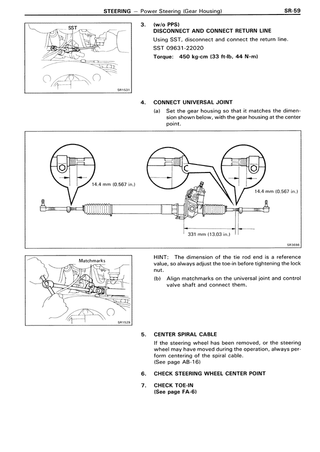
4. CONNECT UNIVERSAL JOINT
(a) Set the gear housing so that it matches the dimen-
sion shown below, with the gear housing at the center
point.
[DIAGRAM: Universal joint alignment diagram showing measurements of 14.4 mm (0.567 in.) on both sides and 331 mm (13.03 in.) in center, labeled SR1638]
HINT: The dimension of the tie rod end is a reference
value, so always adjust the toe-in before tightening the lock
nut.
(b) Align matchmarks on the universal joint and control
valve shaft and connect them.
[DIAGRAM: Matchmarks alignment diagram labeled SR1633]
5. CENTER SPIRAL CABLE
If the steering wheel has been removed, or the steering
wheel position is not set during the operation, always per-
form centering of the spiral cable.
(See page AB-16)
6. CHECK STEERING WHEEL CENTER POINT
7. CHECK TOE-IN
(See page FA-6)