INTRO/Introduction & How To Use1 / 6
p.002 →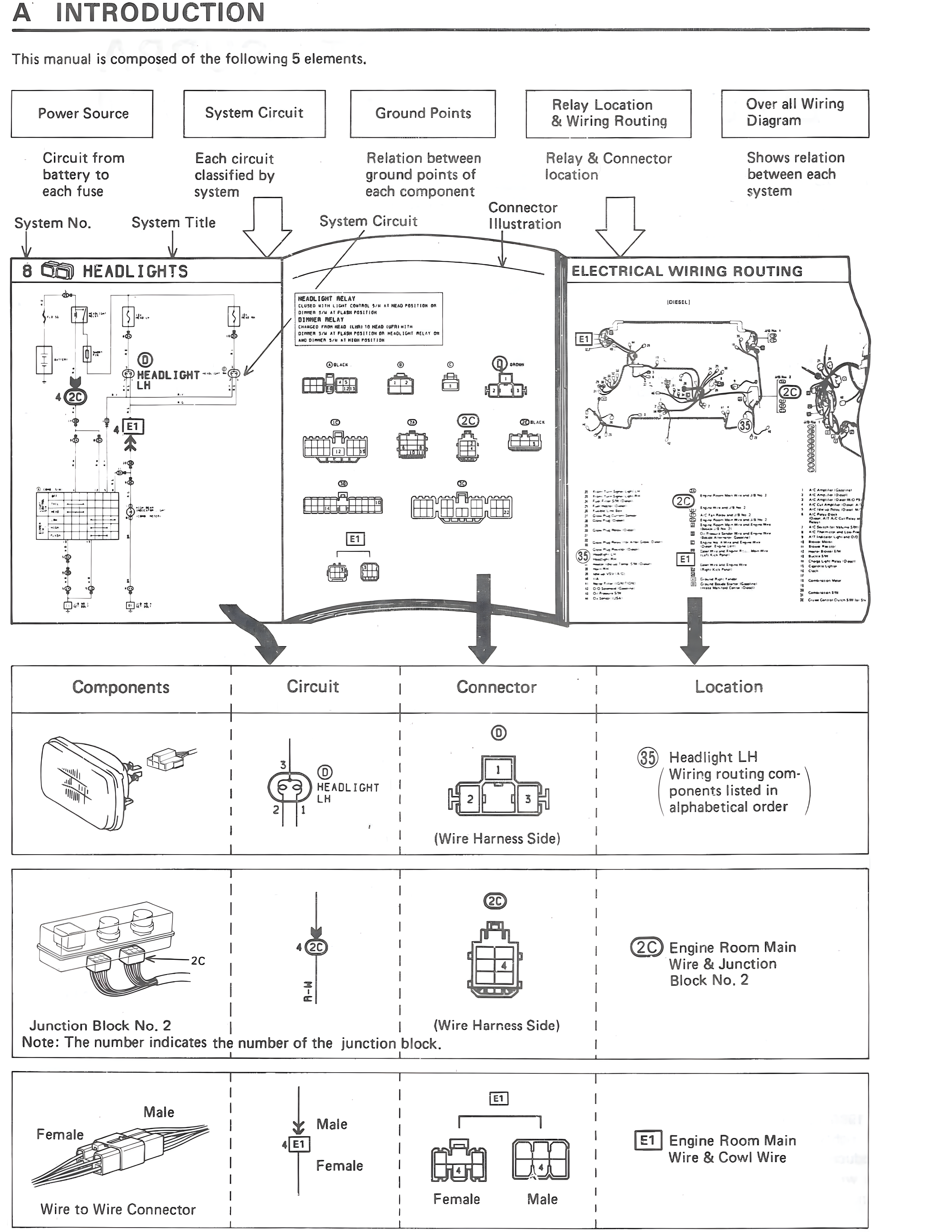
100%
A INTRODUCTION
This manual is composed of the following 5 elements.
Power Source
Circuit from battery to each fuse
System Circuit
Each circuit classified by system
Ground Points
Relation between ground points of each component
Relay Location & Wiring Routing
Relay & Connector location
Connector Illustration
Over all Wiring Diagram
Shows relation between each system
System No. System Title
8 HEADLIGHTS
HEADLIGHT RELAY
REQUIRED WHEN THE TOTAL WATTAGE OF THE LIGHTS EXCEEDS 60
OTHERS: FOR AT FLASH PROTECTION
DIM: 30 AMP FLASH PROTECTION
DIM: TO PROTECT DIMMER SWITCH
DIM: TO PROTECT COMBINATION SWITCH
DIM: TO PROTECT THE BULB TYPE FLASH PROTECTION
HEADLIGHT
LH
ELECTRICAL WIRING ROUTING
(OVERALL)
Components | Circuit | Connector | Location
[Headlight component illustration] | HEADLIGHT LH | D (Wire Harness Side) 1 2 3 | 3G Headlight LH /Wiring routing com- ponents listed in alphabetical order
Junction Block No. 2
Note: The number indicates the number of the junction block. | 4(2C) | 2C (Wire Harness Side) | 2C Engine Room Main Wire & Junction Block No. 2
Wire to Wire Connector
Male
Female | 4(E1)
Male
Female | E1 Female Male | E1 Engine Room Main Wire & Cowl Wire