100%
14 REAR WINDOW DEFOGGER
2.5A GAUGE
RR DEFOG LG
DEFOGGER RELAY
CLOSED WITH IGNITION S/W AT IG POSITION
AND DEFOGGER S/W ON
(A) 3(C) (LHD)
7(L) (RHD)
(D) 3 GM
R
(D)
DEFOGGER S/W
(F) 1 (LHD)
2 (RHD)
1 (LHD)
3 (RHD)
7
1
2
8(G) (LHD)
6(L) (RHD)
B(C) BLACK
(A)
H
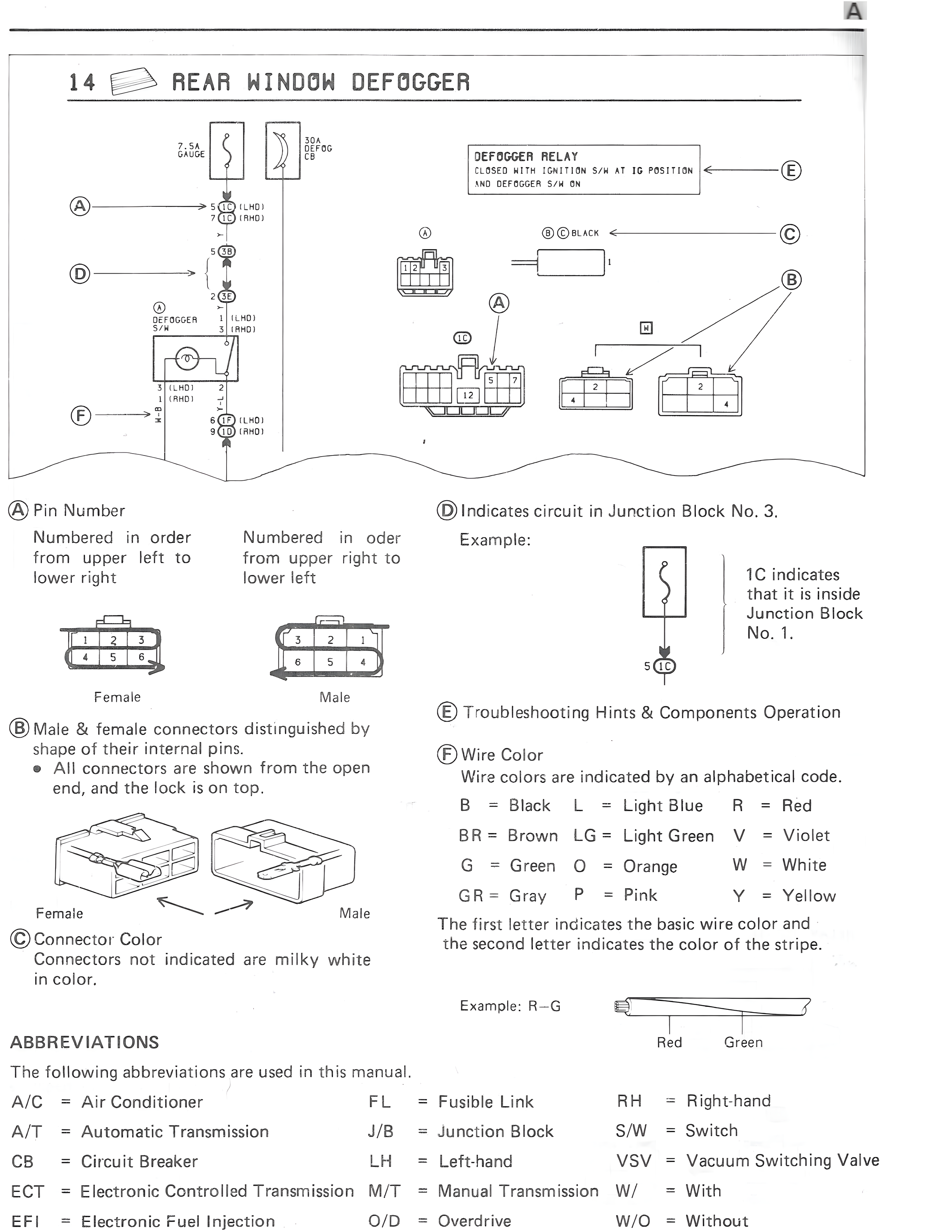
(A) Pin Number
Numbered in order from upper left to lower right
Numbered in order from upper right to lower left
Female Male
(B) Male & female connectors distinguished by shape of their internal pins.
• All connectors are shown from the open end, and the lock is on top.
Female Male
(C) Connector Color
Connectors not indicated are milky white in color.
(D) Indicates circuit in Junction Block No. 3.
Example:
1C indicates
that it is inside
Junction Block
No. 1.
S 1C
(E) Troubleshooting Hints & Components Operation
(F) Wire Color
Wire colors are indicated by an alphabetical code.
B = Black L = Light Blue R = Red
BR = Brown LG = Light Green V = Violet
G = Green O = Orange W = White
GR = Gray P = Pink Y = Yellow
The first letter indicates the basic wire color and the second letter indicates the color of the stripe.
Example: R-G
Red Green
ABBREVIATIONS
The following abbreviations are used in this manual.
A/C = Air Conditioner FL = Fusible Link RH = Right-hand
A/T = Automatic Transmission J/B = Junction Block S/W = Switch
CB = Circuit Breaker LH = Left-hand VSV = Vacuum Switching Valve
ECT = Electronic Controlled Transmission M/T = Manual Transmission W/ = With
EFI = Electronic Fuel Injection O/D = Overdrive W/O = Without