100%
B
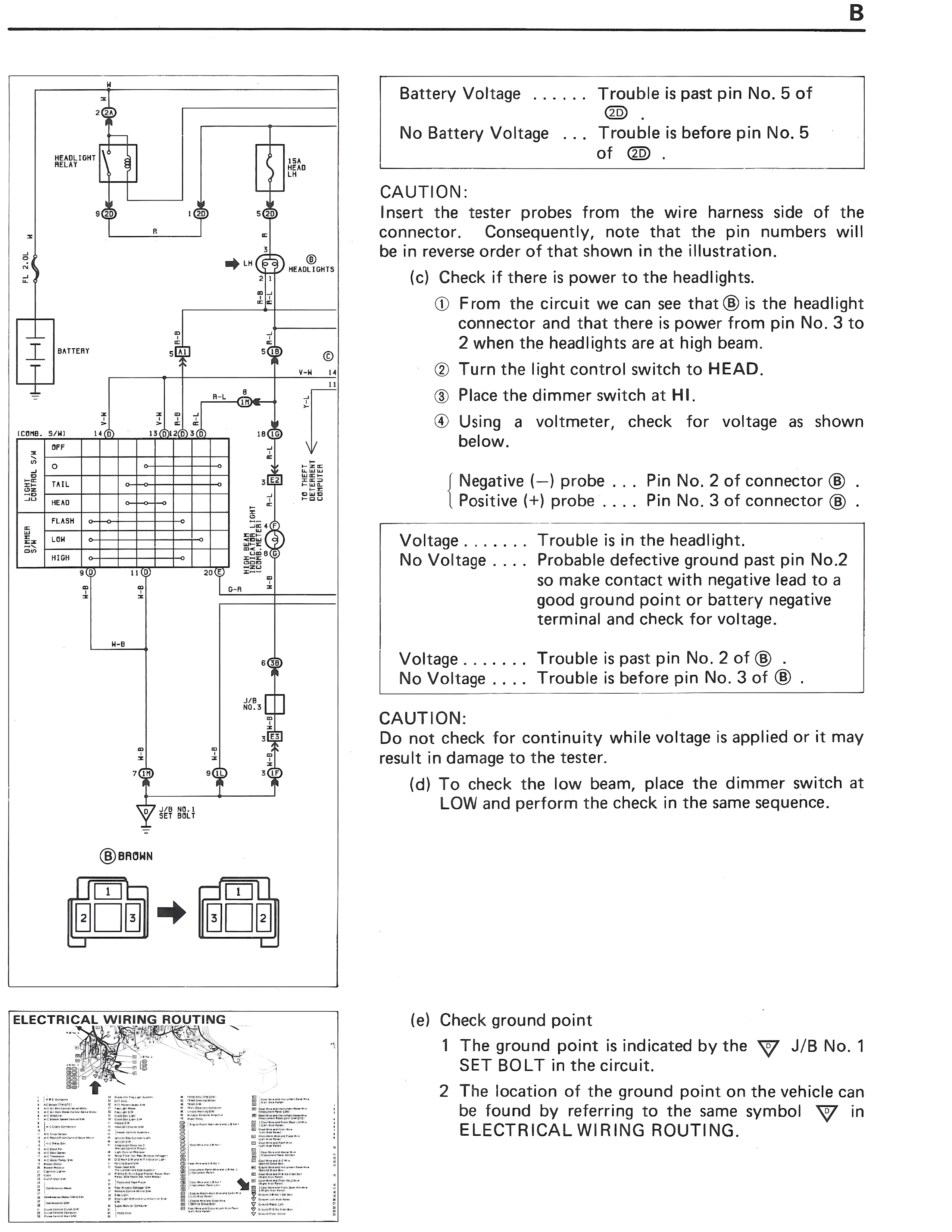
Battery Voltage ...... Trouble is past pin No. 5 of 2D.
No Battery Voltage ... Trouble is before pin No. 5 of 2D.
CAUTION:
Insert the tester probes from the wire harness side of the connector. Consequently, note that the pin numbers will be in reverse order of that shown in the illustration.
(c) Check if there is power to the headlights.
① From the circuit we can see that B is the headlight connector and that there is power from pin No. 3 to 2 when the headlights are at high beam.
② Turn the light control switch to HEAD.
③ Place the dimmer switch at HI.
④ Using a voltmeter, check for voltage as shown below.
Negative (-) probe ... Pin No. 2 of connector B.
Positive (+) probe .... Pin No. 3 of connector B.
Voltage ....... Trouble is in the headlight.
No Voltage .... Probable defective ground past pin No.2 so make contact with negative lead to a good ground point or battery negative terminal and check for voltage.
Voltage ....... Trouble is past pin No. 2 of B.
No Voltage .... Trouble is before pin No. 3 of B.
CAUTION:
Do not check for continuity while voltage is applied or it may result in damage to the tester.
(d) To check the low beam, place the dimmer switch at LOW and perform the check in the same sequence.
HEAD LIGHT RELAY
HEAD
TAIL
HEAD
FLASH
LOW
HIGH
OFF
LH
BATTERY
R-W
B-H
(CONT. 5/26)
BATTERY
SWITCH
LIGHT
CONTROL
SWITCH
B
DIMMER SWITCH
LH IG
B-W
V-M
FUSIBLE
LINK
D
HEADLIGHTS
HEAD
LIGHT
FLASH
RELAY
METER
COMBINATION
METER
HEAD
HI
IND.
HEAD
LIGHT
RELAY
J/B No.1
B BROWN
ELECTRICAL WIRING ROUTING
(e) Check ground point
1 The ground point is indicated by the ▽ J/B No. 1 SET BOLT in the circuit.
2 The location of the ground point on the vehicle can be found by referring to the same symbol ▽ in ELECTRICAL WIRING ROUTING.